
Abstract
In the context of collaborative robotics, distributed situation awareness is essential for supporting collective intelligence in teams of robots and human agents where it can be used for both individual and collective decision support. This is particularly important in applications pertaining to emergency rescue and crisis management. During operational missions, data and knowledge are gathered incrementally and in different ways by heterogeneous robots and humans. We describe this as the creation of Hastily Formed Knowledge Networks (HFKNs). The focus of this paper is the specification and prototyping of a general distributed system architecture that supports the creation of HFKNs by teams of robots and humans. The information collected ranges from low-level sensor data to high-level semantic knowledge, the latter represented in part as RDF Graphs. The framework includes a synchronization protocol and associated algorithms that allow for the automatic distribution and sharing of data and knowledge between agents. This is done through the distributed synchronization of RDF Graphs shared between agents. High-level semantic queries specified in SPARQL can be used by robots and humans alike to acquire both knowledge and data content from team members. The system is empirically validated and complexity results of the proposed algorithms are provided. Additionally, a field robotics case study is described, where a 3D mapping mission has been executed using several UAVs in a collaborative emergency rescue scenario while using the full HFKN Framework.
1 Introduction
The importance of effective communication and efficient data/knowledge transfer is essential for the coordination of life-saving activities in regions affected by natural or man-made disasters. The organizations and groups involved range from disaster relief, governmental and non-governmental organizations at the macro level, to actual teams of emergency rescue responders on the ground at the micro-level. Emergency rescue teams have recently been supported by heterogeneous robotic assistants. There are an increasing number of natural disasters that include wild fires, hurricanes, earthquakes and floods that require state-of-the-art emergency response to minimize loss of life and property damage.
In a seminal article, Denning [1], pointed out the importance of establishing Hastily Formed Networks (HFNs) in the broader sense as "the ability to form multi-organizational networks rapidly" and as being crucial to disaster relief. Here, Denning’s focus was on effective human communication rather than efficient data/knowledge transfer, and the use of autonomous systems in emergency rescue operations was not yet prevalent. Additionally, the term conversation space was introduced for the medium in which such communication takes place.
Experience has shown that first response is dependent on the quality and nature of this conversation space. This space is intended to provide a medium for acquiring situation awareness and the original concept was very much focused on setting up the physical layer for communication. Proposed components of the conversational space were the physical systems, the players involved and the interaction practices. The latter include situation awareness, acquiring and sharing information, planning, making decisions, coordination, and command and control required by the players and teams involved.
Using Denning’s metaphor of Hastily Formed Networks for enhanced communication and conversation spaces among human agents in emergency rescue operations as a starting point, we extend the idea in two ways using the term Hastily Formed Knowledge Networks (HFKNs) as a guiding metaphor for this research.
-
Firstly, rather than focusing solely on teams of human agents, we focus on teams of human and heterogeneous autonomous robotic agents interacting in various ways among themselves and with humans to make rescue operations more efficient and to achieve collaborative goals.
-
Secondly, rather than just focusing on communicative aspects and conversational spaces for crisis communication, we instead focus on both communicative aspects and data/knowledge aspects in data/knowledge interaction spaces among collaborative teams consisting of both human and robotic agents.
The goal is to automate the goal-driven creation and exchange of local and global situation awareness among team members (both human and robotic) in addition to improving the basis for informed decision making by providing timely data and knowledge rich contexts for doing this. These data and knowledge contexts will be both individually and collaboratively constructed on-the-fly during the unfolding of emergency rescue missions relative to the needs and requests of human and robotic team members.
The work presented in this paper is part of a larger infrastructural multi-agent based framework being developed with the goal of leveraging the use of heterogeneous teams of human agents, Unmanned Aerial Vehicles (UAVs), and surface and ground vehicles. The intent is to provide situation awareness, services and supplies to emergency rescuers on the ground in collaboration with other human resources in disaster relief scenariosFootnote 1.
Much of the recent work with collaborative human/robotic systems [2–8] has focused on the representation and generation of shared tasks and shared goals and how such shared goals can be achieved through the coordination of agents participating in such shared tasks. In other work, we have considered this and developed a delegation-based framework for task generation, allocation, and execution for collaborative robotics [9–11]. In fact, these earlier results will be used together with the work presented in this article, for supporting collaborative data collection tasks and other types of missions. The delegation framework will be used to setup distributed data collection, distribution, and synchronization of tasks among teams of robotic and human agents. These data stores then contribute to a shared situation awareness of different aspects of the operational environment that can be used by robotic and human agents alike in other tasks associated with emergency rescue.
1.1 SymbiCloud HFKN framework
The focus of this paper is the SymbiCloud HFKN Framework, which includes a data/knowledge management infrastructure that is intended to be used to support distributed, collaborative collection of data and knowledge and its shared use in multi-agent systems. In this framework, each agent is assumed to have a SymbiCloud module (SCModule) containing its local or contextual perspective of its operational environment. This module can include geographically tagged information, sensor-data abstractions, 3D maps, static and dynamic object representations, and activity recognition structures, in addition to a rich set of reasoning engines and data/knowledge management processes. An agent’s SCModule content will vary according to its capabilities, its sensors, and its ability to gather information. An agent’s data/knowledge perspective can be enhanced and extended through interaction and synchronization with other agent’s data/knowledge perspectives. These shared perspectives provide enhanced situation awareness for individual team members.
Given a team of agents, information in SCModules can be aggregated and merged dynamically and virtually at different abstraction levels to allow for richer perspectives to improve timely decision making and planning processes for the individual agents and teams. The Symbi in SymbiCloud is intended to emphasize that we would like to semantically ground as much data and knowledge as possible. The Cloud in SymbiCloud is intended to emphasize the highly distributed and fluid use of data and knowledge across individual team members and the goal of leveraging developments in Cloud-based technology in a wider perspective, where parts of an agent’s SymbiCloud module may be stored and accessed using Cloud services. Additionally, agents with SCModules can access useful and relevant information directly from the Internet such as Semantic Web content and combine it with an agent’s locally stored knowledge.
Figure 1 provides a high-level schematic of the basic data/knowledge functionality we are interested in providing for teams of human/robotic agents. In this figure, there are four agents, one human agent, one Unmanned Surface Vehicle (USV) and two Unmanned Aerial Vehicles (UAVs). Each agent has the functionality to generate and share collaborative tasks through the use of a distributed delegation framework that is part of the HFKN Framework which allows for generating, synchronizing, querying, and sharing of the data/knowledge among agents.

High-level schematic - the collaborative robotics framework assumes that each participating agent has a Delegation Module and a SymbiCloud Module. Agents on a team generally communicate via speech acts. Each agent is assumed to be using a communication middleware such as ROS while generating distributed tasks and distributed situation awareness
For the purposes of this paper, one can abstract the distributed knowledge network from the high-level schematic depicted in Fig. 1. This aspect of the framework is shown in Fig. 2.

In a multi-agent system, distributed information resources can be viewed as a dynamic graph that can grow and shrink as agent members enter and exit a particular mission in an operational environment
Each agent in the system is assumed to have associated with it, an SCModule. Additionally, it is assumed that each robotic agent uses a communication framework, such as ROSFootnote 2 [12]. Each SCModule stores the local or contextual situation awareness of an agent, structuring associated data and knowledge at different levels of abstraction. An SCModule can in part, be viewed as a generalization of a layered Geographical Information System (GIS), but with a much richer variety of data and knowledge structures and more general querying mechanisms to access information in SCModules. Additionally, SCModules include a KDB Manager for synchronizing and merging information and knowledge content across agents.
Robotic and human agents are intended to have access to data, information and knowledge at many different levels of abstraction ranging from low-level sensor data, such as range data in single scans from LIDAR (Laser Imaging Detection and Ranging sensor), or collections of images from camera sensors. Intermediate levels of data and knowledge may contain 3D or infrared maps, that are the result of post-processing of low-level sensor data. These structures may in turn be semantically labeled with identifiable geolocated objects and additional semantic properties. Relations between such objects may then be defined and information stored about both static and dynamic activities of such objects. High-level semantic representations provide qualitative models possibly grounded in lower-levels of the knowledge and data abstractions associated with an agent.
In actual emergency rescue scenarios, there are a number of important contingencies that arise that make the design and implementation of the functionalities included in the HFKN Framework relatively complex:
-
Unreliable communication between agent systems.
-
Out-of-range issues between agent systems.
-
Agent systems entering and exiting operational environments dynamically.
-
Agent systems turning off for such activities as recharging or refueling.
-
Queries that return no data, or only partial data in the context of data required by the querying agent.
Such contingencies present an additional level of complexity in designing the functionalities of interest. These issues must be dealt with in order to build robustness and resiliency into the framework design and use. Some of these issues can be dealt with by leveraging existing communication functionality in middleware such as ROS/ROS2, but other aspects must be taken into account in the associated algorithms as will be shown.
1.2 Contributions and content
The paper includes the following contributions:
-
A description of a general system architecture (SymbiCloud HFKN Framework) for supporting multi-modal data/knowledge storage, in addition to the dynamic aggregation, sharing, transfer and querying of such data/knowledge in multi-agent contexts consisting of human and robotic agents. Information ranges from low-level sensor data collected by robotic sensors to high-level semantic knowledge.
-
An integration of an existing delegation-based multi-agent framework with the HFKN Framework that together is used for automatic generation and execution of collaborative data/knowledge-collection tasks.
-
An integration of an RDF (Resource Description Framework) Graph Synchronisation System which allows for the automatic distribution and sharing of information and knowledge between agents.
-
A data-transfer algorithm and protocols for exchanging datasets of low-level sensor data among agents based on the use of metadata about such datasets.
-
An empirical evaluation of the HFKN Framework and associated algorithms.
-
A field robotics emergency rescue case study based on a multi-agent data collection mission that uses all described functionalities of the HFKN Framework.
The paper is structured as follows. In Section 1, the basic context for this work in addition to a conceptual description of the HFKN Framework has been introduced. In Section 2, a brief summary of the Delegation Framework used by the HFKN Framework is described. In Section 3, the structure and content of SCModules, that provide the data and knowledge content of agents is presented. In Section 4, the concept of a dataset which specifies a collection of sensor data in addition to its metadata description is provided. In Section 5, a brief overview of the RDF Graph Synchronisation (RGS) System and its integration in the HFKN Framework is presented. In Section 6, the processes executed by agents to exchange low-level sensor data via a dataset transfer protocol is presented. In Section 7, a field robotics case study with collaborating UAVs and human agents that display the power of the HFKN Framework in actual robotic scenarios is described. Sections 8 and 9 provide a description of related work and conclusions, respectively. The paper also includes two appendices that provide detailed descriptions of schemas used in SCModules and examples of complex SPARQL queries that can be expressed by the system.
2 Brief summary of the delegation framework
In the introduction, we provided an overview of the HFKN Framework which is the focus of this article. It is a framework for collaborative robotics which leverages the use of a delegation framework [9, 11, 13, 14] for generating and executing complex, multi-agent distributed plans and tasks. An overview of the full architecture that combines the two is shown in Fig. 1. In order to understand how the HFKN Framework leverages the delegation framework, it is important to have a cursory understanding of this framework. This section is intended to do that.
As in the case of the distributed knowledge network, one can abstract an instance of the distributed delegation network, from the high-level schematic depicted in Fig. 1. This aspect of the framework is shown in Fig. 3.

In a multi-agent system, the distributed task generation and execution network can be viewed as a dynamic graph that can grow and shrink as agent members enter and exit a particular mission in an operational environment
In the delegation framework, each member of a collaborative team is assumed to have a Delegation Module associated with it. An agent’s Delegation Module contains a Delegation Manager that manages the external interactions with other agents on the team, in addition to internally managing the generation and execution of composite tasks [10]. Figure 4 provides a high-level characterization of the internal architecture of a Delegation Module.

Delegation Module associated with each collaborative agent on a team
Given a high-level mission goal specification, provided by a member of the team, the purpose of the delegation framework is to dynamically generate a task specification (often distributed among agents) to achieve the goal. This task specification often involves the use of a subset of members of the team. The task specification is generated recursively through a process where participating team members agree to do a part of the mission if they have the required resources and are able to commit to doing that part of the task specification. Each team member has the ability to broadcast for help in achieving sub-tasks associated with the larger mission specification. If successful, the net result of the process is the generation of a task specification where different parts of the specification are allocated to appropriate members of the team.
Tasks are represented as Task Specification Trees (TST) [10, 15]. A TST consists of a set of control nodes and a set of elementary actions (leaf nodes) provided by participating members of the team. For simplicity, control nodes can be viewed as standard forms of control in programming languages such as sequence, concurrency, if-then, etc. During the delegation process, a tree is constructed recursively through calls to participating agents where they contribute to the overall task by providing sub-trees they are able to commit to and execute.
It is assumed that each agent publicly commits to a set of elementary and composite actions that can be used in the collaborative delegation process. In the case of UAVs, examples of elementary actions would be such actions as FlyTo, TakeOff, or Land. Composite actions might consist of more complex activities such as scanning of a region, that although internally complex for the agent, are viewed externally as elementary actions that can be used by the team to generate more complex task specifications collectively.
Figure 5 depicts an example of a TST generated for a concurrent scanning mission consisting of two UAV agents.

TST generating a concurrent scan by a fixed-wing and a rotor-based system. A Test-If node first checks if the rotor-based system is on the ground or in the air. From the agent’s perspective, a Scan-Ground-Single task is a composite action, while from the delegation perspective it is an elementary action
Each Delegation Module as shown in Fig. 4 consists of four conceptual components:
-
Delegation Manager - It provides inter-agent communication to other members of the team during the delegation process. Internally, it accesses the TST Factory to generate TST nodes during the TST generation phase and the TST Executor factory to execute TSTs during the execution phase.
-
TST Factory - It has the ability to generate TST nodes and TST sub-trees during the TST generation phase in the delegation process.
-
TST Executor - Associated with each elementary or composite action publicly declared by an agent, is a platform dependent executor that interfaces to an agents internal functionality. The TST executor is responsible for interfacing to and managing the execution of executors associated with elementary or composite actions for a specific platform. If a TST node is a goal node type, the TST executor also has the possibility to interface with an automated planner associated with a platform to generate a sub-tree from the planner that can then be used by the TST factory.
-
Constraint Server - TST nodes can contain constraints that are inherited as the delegation process progresses. In order for an agent to answer the question “can I do this?” when it receives a request from another agent, it autonomously sets up a constraint problem and checks the problem for consistency, possibly returning specific variable bindings. The constraint server handles this part of the generation process. For instance, constraints can be temporal, resource based, or associated with sensor capability.
In the context of the HFKN Framework, the delegation functionality will be used to generate and execute distributed information gathering and manipulation tasks for teams of collaborative humans and robots. Examples of information gathering and manipulating TSTs will be described in the field study, presented in Section 7.
3 SymbiCloud modules
SCModules are associated with each agent and store combinations of data, information and knowledge. Additionally, SCModules are responsible for sharing, synchronizing and aggregating data, information and knowledge between agents.
We characterize three types of data (in the general sense) loosely coupled to the concepts of data, information and knowledge that are acquired, stored, aggregated and shared by agents (see Fig. 6):
-
Low-level sensor data characterizes raw output from diverse sensors. Examples include data in images from camera sensors or point data in single scans from LIDAR systems.
Fig. 6 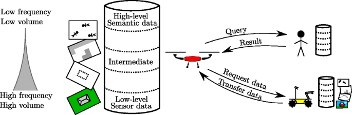
In a multi-agent system each agent is equipped with its own SCModule providing its particular perspective of the world. To participate in collaborative missions it is often necessary for agents to access information from other agents’ SCModule such as query for knowledge stored or request the transfer of data
-
Intermediate data characterizes processed raw data with minimal to moderate structure. Representation of such data are often collections of feature/value pairs stored in tables but could also be the output of sensor fusion algorithms such as point clouds and 3D maps.
-
High-level semantic data characterizes data generally structured around objects with properties and relations between objects. Such data is normally semantically grounded. Common examples would be ontological structures, logical structures, or graph-structured knowledge. Objects representing humans identified in search and rescue missions with feature data associated with each human is a good example.

These different types of data pose different requirements on storage, synchronization and query mechanisms due to each having different characteristics. Low-level sensor data is typically very well structured and normally acquired in high volumes with high frequency. It is important that efficient data structures are used for storage and retrieval. This data is typically retrieved with simple queries by requesting sets of ordered and timestamped data points. High-level semantic data, on the other hand, requires low-volume for storage and is normally generated with low frequency, but it requires more complex query mechanisms. High-level semantic knowledge require structures and representations suitable for distributed querying, merging and synchronization. Figure 6 depicts this informatic situation for several agents.
Each SCModule as shown in Fig. 7 consists of three conceptual components:
-
A PostgreSQL database - This database generally stores low-level sensor data and intermediate data, in addition to any table-based information used by the agent.
Fig. 7 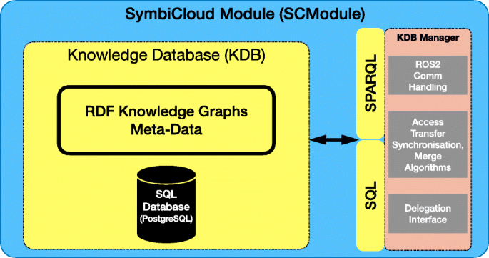
SCModule associated with each agent
-
A repository of RDF Documents/Graphs - This RDF Document/Graph repository includes both object-level semantic content in addition to metadata representations of low-level sensor data and intermediate-level data stored in the PostgreSQL database. They are these structures that will be shared and synchronized between agents by the Knowledge Database Manager.
-
A Knowledge Database (KDB) Manager - The KDB Manager is responsible for the management of the PostgreSQL database and the RDF Document/Graph repository. It also supports communication with other agents and handles dataset generation processes, in addition to the execution of synchronization and dataset transfer algorithms between agents.

In order to represent high-level semantic information, SCModule’s use the Resource Description Framework (RDF) [16]. RDF provides a representational foundation for the Semantic Web and was developed within the World Wide Web Consortium (W3C). The RDF framework has a very simple, but powerful set of representational primitives. Most important are RDF Triples consisting of a subject, predicate and object. Subject and object are nodes in an RDF Triple and predicate is a label for the edge connecting them that expresses a relationship between the subject and the object. Subject and predicate are specified using Internationalized Resource Identifiers [17] (IRI’s), that provide a unique identity to any subject or predicate, while object can have any value including an IRI.
It is useful to view RDF Triples graphically (see Fig. 8), since collections of such interconnected triples can be conceptually viewed as RDF (knowledge) Graphs. Logically, an RDF Triple (subject, predicate, object) to an atomic formula, predicate(subject, object). This correspondence is very powerful since it provides formal semantic interpretation of collections of RDF Triples as logical theories. There are many extensions to the RDF specification such as RDF Schema (RDFS) [18] and the Web Ontology Language OWL [19] which extends RDFS and is used for specification and reasoning about ontologies.

Components in an RDF Triple
Although a collection of RDF Triples can be viewed as an RDF Graph, such graphs are encoded as RDF Documents. Consequently, we use the terms RDF Document and RDF Graph more or less interchangeably in the paper. In [20], we present an extended version of an RDF Document, denoted RDF ⊕ Document, that is given as input to the RGS System used to synchronize shared RDF Documents between agents. A common way to store and access content in an RDF Graph is to store the triples in an SQL database, create appropriate RDF Views for the content, and then use SPARQL (SPARQL Protocol and RDF Query Language) [21] together with these RDF Views to query RDF Graphs.
This is the approach we take. The KDB Manager in an agent’s SCModule provides the ability for the agent, and other external agents, to access and query RDF Graphs through the use of SPARQL. From an implementational perspective, all RDF Graphs are represented in table form in the PostgreSQL database. In this case, the KDB Manager has a library of views (schemas) created using RDF View [22]. RDF View provides a means of automatically converting any SQL table into a set of RDF Triples. The Sparqlify language [23] is used to specify RDF Views.
Low-level sensor data and intermediate data is stored in SQL tables in order to efficiently support high volume and frequency data storage and retrieval via use of a PostgreSQL database and its associated SQL query language. Theoretically, one could translate any SQL tables into RDF Graphs, but it has been shown that SQL databases have on average between 5 to 10 times higher performance than SPARQL databases [24]. This is one reason we retain a conceptual separation between low- and intermediate-level data, with high-level semantic data in the KDB.
Although an agent can also access raw sensor data in the PostgreSQL database via the KDB Manager using SQL (or SPARQL, if the requisite RDF Views have been created), such direct querying of raw data has limited usage in the types of missions we envision. Instead, collections of raw data are bundled as a dataset and information about its contents is represented as metadata using RDF Graphs. Metadata in this context is high-level semantic information about a collection of sensor data acquired by an agent during an information gathering mission. Agents query metadata about respective datasets in order to determine what raw sensor data a team of agents has collected. Datasets represent only a subset of information an agent can have, but this form of information and its conceptualization as a dataset, is practical and efficient in data-collection missions.
Each agent has the ability to declare RDF Documents in its KDB as public or private. Only the public information will be accessible to other agents. One could imagine more fine-grained dynamic approaches to access-control, such as mission-based or agent role-based access control, but this is left for future work.
A more query-centric and implementational view of the SCModule is shown in Fig. 9. All raw sensor data, intermediate- and high-level semantic data resides in the SQL Database (PostgreSQL). The low-level data is stored using tables with a schema specific to the type of data, while the high-level symbolic data is stored in tables with a schema suited for storing RDF Triples. These components are visualized with blue boxes in the figure.

More detailed SCModule architecture for a single agent. All data is stored in SQL tables, and it can be queried through SQL or through semantic queries (SPARQL). The application layer handles interfaces between the KDB and a robot, a human or general sources of knowledge such as the Semantic Web
The KDB provides four types of APIs to access the data stored in the SQL Database (orange boxes in the figure). First, a high-level mapping between tables and programming language objects is provided using Active Record [25]. Second, the data in tables can be queried directly using SQL. The two remaining APIs are compatible with Semantic Web technologies. Namely, SPARQL in combination with RDF Views and RDF/XML, Turtle (or other formats) can be used to access data represented as RDF Triples in the SQL Database. These interfaces are used by the KDB Manager, user interfaces or external Semantic Web frameworks. In an SCModule, the application layer and the query interface for the KDB are handled by the KDB Manager.
4 Datasets
The focus of this paper is on complex data collection missions using multiple robotic systems with human interaction. Consequently, we specify a special structure, a datasetFootnote 3, that is the result of any data collection mission. Additionally, agents usually require specific subsets of raw or intermediate data specified as datasets for decision making processes during mission operation. For example, an agent may want to access part of a 3D map or an orthophoto associated with a specific region in an operational environment. Consequently, datasets should be able to be created dynamically as subsets or aggregations of already existing datasets.
The description of a dataset is characterized by high-level semantic information which describes, references and annotates low- or intermediate-level data structures. Each dataset is identified by a unique Uniform Resource Identifier (URI). This metadata description is stored as an RDF Graph. High volume data, such as point clouds, images, etc., cannot generally be exchanged efficiently between agents at periodic intervals, but metadata about datasets can be efficiently exchanged.
Raw sensor data collections are grouped in datasets consisting of the actual raw sensor data that is stored in a PostgreSQL database and the associated metadata represented as an RDF Graph. In the synchronization processes managed by the KDB Manager, it is the metadata associated with datasets that is synchronised between agent platforms. When an agent does need to access and acquire actual raw sensor data from another agent, the agent would need to make an explicit request that the sensor data should be downloaded from another agent using the Dataset Transfer Protocol presented in Section 6.
4.1 Dataset representation
A dataset \(\mathcal {D}\) consists of a set of data points {di} which can be:
-
Raw sensor data, such as images and image sequences, LIDAR scans, IMU frame sequences, GPS positions, robot poses, etc.
-
Results of sensor fusion algorithms that combine different types of raw data, such as a sequence of robot poses that use both IMU and GPS data, or the locations of humans or building structures, derived from complex classification algorithms.
-
Any other high-volume data acquired from external services, such as systems based on Semantic Web or GIS technologies.
Data points are stored in database tables according to their types. The tables contain a set of fields that are specific to the type (for instance, IMU contains fields for linear acceleration and angular velocity, as well as covariances). All data points are associated with the URI of the dataset they belong to.
Dataset descriptions are defined using a collection of RDF Triples:
-
An URI of a dataset, for example ex:dataset1.
-
A geometry corresponding to the area covered by the dataset, for example: (ex:dataset1, geo:hasGeometry, "POLYGON((...))").
-
A type indicating the type of data, for example, image, LIDAR scan, victims (salient points representing potential victim locations): (ex:dataset1, aiics:dataset_type, aiics:points_cloud).
-
A list (possibly empty) of other datasets (URIs) included in this dataset. This is useful to allow the modular structuring of a dataset into smaller component datasets: (ex:dataset1, aiics:dataset_include, ex:dataset1)
(ex:dataset1, aiics:dataset_include, ex:dataset 2).
Figure 10 shows an example RDF Graph representing metadata for two point cloud datasets, where one is a subset of the other. For more examples of sensor data representations, see Appendix A Representation of data structures in SCModules.

RDF Graph representing metadata for two point cloud datasets, where ex:dataset 2 is a subset of dataset ex:dataset1
4.2 Dataset relation to agents
Given a team of agents, each agent stores a collection of RDF Graphs as part of the KDB in its SCModule. The union of collections of these RDF Graphs virtually represents the global knowledge of a team of heterogeneous agents. Since, the data/knowledge is distributed in multiple databases and owned by different agents, no agent has direct local access to the complete spectrum of information associated with a team. In order to gain access to the required information necessary for achieving a specific mission goal (e.g. a global map of the operational environment), the agents have to collaborate to fully (or partially) synchronize their data/knowledge resources, or to eventually exchange raw sensor data. The synchronization process is intended to be fully automated. It occurs asynchronously, in particular when a team member updates a public RDF Document subscribed to by other agents.
Each agent is identified uniquely by its own URI. Datasets are coupled to specific agents by the creation of RDF Triples that relate the unique agent URI to datasets (also stored in RDF Graphs) via the following relations:
-
has - which indicates that an agent has a copy of the raw data associated with the dataset in its database.
-
created_by - which indicates which agent has acquired or processed raw data.
-
created_from - which indicates that a dataset was created using raw data from another dataset. For instance, a point cloud can be the result of combining multiple LIDAR scans together from different agents.
Figure 11 shows an example of a set of datasets owned or shared by two UAV platforms and one human operator.

An example of a set of datasets and the relationship between them. There are three datasets (in blue) resulting from an exploration mission, created by two UAVs. A point cloud dataset (in orange) was created by fusing two LIDAR scan datasets. A building dataset (in green) was created by processing the point cloud and an image dataset. The graph shows how each dataset was created and also which agent currently holds a copy of a dataset
4.3 Dataset discovery
Agents are aware of their team members via their unique URIs and by leveraging identification functionality in the framework. Additionally, as agents act in operational environments and create datasets, each maintains an RDF Document listing those datasets and other information publicly available. A publish-subscribe ROS-based strategy is used to declare publicly accessible documents that can be subscribed to by any agent. An agent’s RDF Document listing public datasets is published by default. Generally, an agent subscribes to all public datasets specified by this RDF Document for each team agent, although the subscription strategy can be modified by any agent at any time.
This team awareness implies that agents have the ability to query each other locally through SPARQL interfaces managed by their KDB Managers. For instance, if one agent is interested in a specific geographical region, it can use its synchronized shared information and discover what type of information and data associated with that geographical region is available from the team.
Figure 12 shows an example of a set of multiple synchronized datasets created and partially shared by a team of agents and how they subscribe to the relevant RDF documents of interest (datasets).

Example illustrating a team of four agents creating datasets and synchronizing selected metadata among themselves. The data stored in an agent is represented by gray boxes. Agents store different types of data (e.g. images or LIDAR scans) as datasets and the metadata associated with each dataset is represented as an RDF Graph. Each agent stores different datasets and it subscribes to selected documents. The dashed line shows examples where RDF Graphs are synchronised between agents
In order to exchange the actual raw sensor data associated with a dataset as described by its metadata, the delegation framework is used with a TST (Task Specification Tree) containing two nodes for uploading and downloading raw data between the corresponding agents. In the Delegation Framework, a TST is both declarative and executable, so such TSTs essentially drive the execution of dataset transfer processes. Downloading is executed on the agent receiving the data, where it first sets up the proper data storage capability. Uploading is executed on the agent sending data, where it extracts the specific data in its KDB and then sends it on the network to the receiving agent. The Dataset Transfer Protocol and processes are described in Section 6.
4.4 Datasets and multi-Agent data collection missions
In a typical collaborative exploration scenario, each agent explores part of the environment, stores data collected during a mission locally, and shares meta-information about the collected data as a dataset with other agents that subscribe to that dataset. Raw sensor data is only exchanged between agents if required. Some examples of when an agent would need large quantities of raw sensor data would be for visualization by a ground operator, for backup purposes, or for further processing such as extracting higher-level semantic information from the raw data. This could involve people identification or classification of building structures which would use specialized algorithms local to an agent.
Figure 13 shows a typical data collection mission evolution from the perspective of the data/knowledge that is locally available to several interacting agents. The setup involves two UAVs and one human operator. As can be seen, metadata about collected sensor data is synchronized between agents continuously while actual sensor data is exchanged only if an agent explicitly requests it. This is a by-need strategy. These two processes are considered in detail in the following two sections.

A timeline illustrating an example collaborative exploration scenario involving two UAVs (UAV 0, UAV 1) and a human operator (OP). The UAVs perform two missions independently at different time points. The metadata describing collected sensor data is synchronised between all three agents after each mission is completed. The datasets collected during Mission 0 and Mission 1 are only available on a UAV which performed the respective mission. At the end the OP would like to visualise both datasets and requests to download the sensor data from each UAV
5 RDF graph synchronization
In the HFKN Framework, high-level semantic information is represented as RDF Graphs, which are encoded as RDF Documents. An RDF Document can contain one or more RDF Graphs. Lower-level data, for example, from sensors, is handled differently as described in the previous sections. This split allows for efficient low-bandwidth/high-level knowledge synchronisation and on-demand access to high-bandwidth raw sensor- and intermediate data.
Agents use RDF Graphs to store various types of information, such as list of salient objects, metadata about datasets (Section 4), general knowledge useful for decision making and planning [26], etc. Throughout a mission, agents make changes to these RDF Graphs. For instance, while collecting sensor data and processing it, an agent will need to update the metadata of the associated dataset. To achieve a common view of the agents’ shared knowledge the HFKN Framework requires an efficient and robust RDF Graph Synchronization (RGS) System that will enable agents to synchronize their RDF Graphs.
The requirements for the RGS System used by the HFKN Framework are driven by constraints and practical demands of in-the-field search and rescue operations, such as unreliable communication and limited bandwidth. The RDF Graph synchronization approach has to have two fundamental properties to account for the communication constraints. First, the RGS process needs to be fully automatic and cannot rely on any human intervention. This property is associated with the fact that communication between robotic agents and command and control centers or human agents is not guaranteed at all times. Second, the system has to handle situations where the set of agents participating in the synchronization process can change over time due to communication interruptions or as agents join or leave missions.
To fulfill these requirements, an automatic and decentralized RDF Graph Synchronization System, called RGS ⊕ [20] has been developed. Its design was inspired by solutions used in code versioning systems such as GIT. The RGS ⊕ System is capable of automatically, promptly, and continuously integrating knowledge created by the agents. The system is also robust against interruptions in communication and agents joining or leaving the synchronization within the collaborative team.
The RGS ⊕ System uses an extended version of the RDF Document concept, called RDF ⊕ Document, which keeps track of a complete history of the changes made by an agent to an RDF Graph. Each change constitutes a revision that is cryptographically signed to authenticate the authorship. The RGS ⊕ System allows agents to advertise selected RDF Graphs made public and shared with other agents. Agents have to explicitly decide to subscribe to a publicly available graph that they are interested in using or contributing to. Figure 14 shows an example where four agents have different local RDF Documents. Agents 0, 1, and 2 synchronize RDF ⊕ Document A, while Agent 3 does not use or contribute to Document A.

RDF Document Synchronisation between four agents
Figure 15 shows a schematic view of the RGS ⊕ System. Internally, the different components of an agent, i.e. Delegation Module, Scanning Module, make changes to the RDF Document during the execution of missions. These changes are broadcasted by the REVISIONDISTRIBUTION mechanism. When new revisions are received by the REVISIONINTEGRATION process, the RGS ⊕ System checks if these revisions can be directly integrated into the RDF Document. If that is the case, the changes are simply applied to the local RDF Graph. If the agent has made changes to its own local copy of the RDF Graph, the received changes need to be combined by merging to avoid potential conflicts. The operation of merging multiple RDF Graph revisions is performed by the merge master which is selected among the set of participating agents. The election process is managed by the MERGEMASTERELECTION mechanism. To decide when an election is started, agents broadcast a status message which allows them to know the composition of the synchronization coalition. Once the merge master is selected, the master requests all necessary revisions to perform the merge operation. The merge operation results are then sent to individual agents to apply them to their local RDF Graph copies.

Schematic view of the RDF ⊕ Document synchronisation mechanism and processes involved
Detailed description of the RGS ⊕ System and its empirical evaluation is provided in [20]. Theoretical analysis and empirical evaluation of the algorithmic complexity of the RGS ⊕ System is described and shown that its algorithms have a quadratic complexity in the number of agents and changes. Realistic scenarios have been tested to demonstrate that the RGS ⊕ System is suitable for synchronizing the metadata of datasets and other types of symbolic data.
6 Dataset transfer protocol
RDF Graph synchronization is used to exchange semantic information and metadata automatically between agents. Bandwidth intensive data, such as point clouds or images are not exchanged automatically. Instead, this kind of lower-level data is encapsulated in datasets and associated with metadata represented as RDF Graphs, as presented in Section 4. The metadata is synchronized between agents using the synchronization protocol described in Section 5. When an agent needs to access the actual bandwidth intensive information, a dataset transfer protocol is used. The focus of this section is on how this is achieved.
An agent is aware of the existence and the location of a dataset from the metadata stored in their local copy of the RDF Graph. The process of downloading the data for local use is achieved through the use of the delegation framework. When the need for data transfer arises, a Task Specification Tree (TST) is generated consisting of two types of nodes:
-
The Send node is instantiated by the agent that has the requested data and is able to provide it to others.
-
The Receive node is instantiated by the agents that require the data.
During the delegation process (see Section 2), which is usually initiated by the receiving agent, a sending agent is selected. As the data can be available from several agents, the criteria for choosing a sender can include constraints such as the battery level, the available bandwidth, or if the agent is expected to stay in communication range. The delegation process results in the generation of the TST shown in Fig. 16. In some cases, multiple agents may want to receive the same dataset. For this reason the TST can contain multiple Receive nodes as can be seen in the figure. The data transmitted between agents is split into chunks and transferred sequentially.

A generic Task Specification Tree (TST) used to transfer the dataset \(\mathcal {D}\) from agent \(\mathcal {A}_{0}\) to agents \(\mathcal {A}_{1},..,\mathcal {A}_{n}\). The Send and Receive nodes are executed concurrently by agents
An overview of the data exchange protocol is presented in Fig. 17. There is only one sender that executes Algorithm 1 and one or more receivers that execute Algorithm 2.

Protocol for transferring datasets
The protocol uses the following messages:
-
The Ready message is used to indicate readiness to receive data.
-
The Data message contains a sequence number, which allows receivers to check whether they obtained all the data, and an array of bytes containing a data chunk of the dataset.
-
The ResendRequest message allows receivers to request missing data chunks.
-
The Error message allows participants to indicate an unrecoverable failure and abort the transfer.
-
The ThrottleUp and ThrottleDown messages allow the receiver to indicate if the sender can send messages faster or slower.
-
The Finished message is sent by the sender to indicate that all the data has been sent. This message contains the last sequence number, so that receivers can check they received all the data.


The agent responsible for providing data operates according to Algorithm 1. It knows the list of receivers from the TST (Fig. 16), and waits for them to be ready (line 1). The sender retrieves the data from its database (line 5) and sends it to the receivers (line 9) until all the data has been sent (line 6), then it sends the finished message (line 20). The sender checks if it has received a request for missing data (line 10) and adjusts the transfer speed up (line 13) or down (line 15) if needed. If the sender receives an error message, it aborts the process (line 17). At the end of the loop, the sender waits (line 19) for the duration τ, to control the data throughput.
An agent receiving the data operates according to Algorithm 2. It starts by sending the ready message (line 1). It then executes the main loop (lines 3–16) that handles the data transfer including error handling, requesting missing data etc. The loop terminates either when the agent receives all data (i.e. receiving of the finished message) or when an error occurs (line 3). The process starts with receiving of the data message (line 4). Based on the sequence number of the received message, a check is done if there is any missing data (line 5), and if that is the case the agent requests it. Before the agent inserts the received data into its database, the validity of the message is checked (line 7). In case the data is invalid the error message is send and the execution of the main loop is interrupted (line 10). The receiving agent can request the sending agent to change the rate at which data messages are sent. This is based on the amount of data messages placed in the reception queue. If the queue has more than a predefined number (e.g. 5) of messages waiting to be processed, the receiver sends a throttle down message (line 11). Otherwise, if the queue is empty it sends a throttle up message (line 13). At the end of the loop, the agent checks if it has received an error message from other agents (line 15). Once the main loop execution is finished, the agent can finalize the insertion of data (line 20). In case the transfer was not successful, the agent removes the received data from its database (line 18).
The combination of the two algorithms used for data exchange guarantees two outcomes: either the dataset has been completely duplicated in all receiving agents, or the transfer has been aborted. During data transfer between two agents, three problems can occur: messages are lost, messages are corrupted, or the communication is interrupted. In Algorithm 2, lost messages are handled by checking the sequence number and requesting potentially missing messages in line 5. Corrupted messages are handled by checking the validity of data, for instance, using checksums, in line 7. Finally, if the communication is interrupted, it will trigger a timeout. Therefore, the finish message will never be received in line 3 and the data exchange will be aborted.
7 Field robotics case study and experiment
The proposed HFKN Framework has been implemented in prototype and validated through a series of experiments both in simulation [20] and in real mission scenarios using multiple UAV platforms. The latter is the topic of this section. We first provide a short description of the UAV platforms used in the field study and then proceed to a description of a multi-agent data collection mission that uses these UAV platforms. We then conclude with a description of the rich set of query mechanisms that are part of the HFKN Framework and have also been used in the field study.
7.1 UAV platforms used in the field test
Two types of UAV platforms were used for experimentation in the case study. The first, shown on the left of Fig. 18, is a modified DJI Matrice 100. It has a maximum takeoff weight of 3.6kg and 1.2kg of payload capacity. The platform measures 100cm between propeller tips. It can fly with speeds up to 22m/s and has a maximum flight endurance of 22 minutes. The platform is equipped with a Hokuyo UTM-30LX LIDAR, which is a single scan device with a guaranteed range of 30m (60m maximum).

Experimental platforms: DJI Matrice 100 equipped with a Hokuyo UTM-30LX LIDAR sensor (left), DJI Matrice 600 Pro equipped with a Velodyne Puck LIDAR sensor (right)
The second type of platform, shown on the right of Fig. 18, is a modified DJI Matrice 600 Pro. It has a 15.1kg maximum takeoff weight, 6kg of payload capacity, maximum flight speed of 18m/s, and 35 minutes of flight time using 5.5kg of payload. It measures 167cm between propeller tips. The GPS system on-board uses a Real-Time Kinematic (RTK) positioning technique to deliver centimeter accuracy measurements. The platform is equipped with a Velodyne PUCK LIDAR sensor, which has an effective range of 100m and uses 16 scan channels. A LIDAR mounting mechanism developed and deployed on the DJI Matrice 600 Pro allows for choosing the sensor orientation depending on the applications or missions at hand.
Both platforms are equipped with the same type of onboard computer system. It is an Intel NUC Kaby Lake i7-7567U CPU platform in a custom enclosure equipped with 16GB of RAM and 500GB SSD of storage. The systems interface with the platforms and run the software modules associated with the Delegation Module and the SCModule. The communication with the ground station for both platforms is realised using 5GHz WiFi connections.
7.2 Field-Robotics case study: collaborative 3D modeling
In this field experiment, we want to demonstrate how multiple agents can explore different parts of an operational environment, share the resulting collected information, and reuse existing information from other missions. The mission leverages functionalities from the HFKN Framework and the Delegation Framework and each robotic agent has a Delegation Module and an SCModule. For human agents, it is assumed that they can interface to the collaborative system through Command and Control centers, or if in the field, through laptops, smartphones, or tablet systems with access to both the Delegation Module and SCModule.
Let’s imagine a scenario where data has been collected during three previous missions. A rescue operator needs a 3D model of a region of the operational environment, for instance, to inspect the state of buildings before planning the next phase of the rescue operation. In such a scenario, the operator will request the HFKN Framework to provide Lidar data for the region of interest. Then the HFKN Framework would provide the data, either by accessing already collected data or by generating and delegating scan missionsFootnote 4 to UAVs. Once the operator has received the Lidar data from the HFKN Framework, he or she can process it to generate a 3D model that can be stored as a dataset in the operator’s local database for future usage.
To demonstrate this scenario, we have divided the experiment into four scan missions shown in Fig. 19 with different types of team interaction and use of collected distributed information:
-
For the first three Scan missions (A, B and C), three different UAVs (UAV0, UAV1, UAV2) are tasked by a ground operator OP to explore non-overlapping areas of the operational environment of interest. This may be done sequentially or concurrently since the regions are non-overlapping. Missions are set up and executed autonomously through the use of the Delegation Framework.
Fig. 19 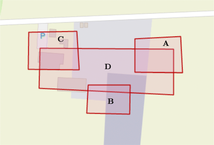
Division into four scan missions A, B, C and D
-
At the end of mission C, the ground operator OP requests the transfer and download of the resulting scanned data from UAV2. This is done using the Dataset Transfer Protocol (Section 6).
-
After viewing a 3D model generated for region C, the ground operator determines that more information is required for a larger region that overlaps with the three previously specified regions, A, B and C.
-
The ground operator OP sets up the fourth mission using the Delegation Framework to gather a full scan of region D by UAV0. Since raw data for regions A, B and C already exists, the fourth mission by UAV0 is automatically tasked to gather data from the region \(\mathcal {D^{\prime }}_{D}=\mathcal {D}_{D}\setminus (\mathcal {D}_{A} \cup \mathcal {D}_{B} \cup \mathcal {D}_{C}) \).

For each Scan mission attempted, the following steps are applied by an agent:
-
First, check if any relevant scanned data is already available in the agent’s KDB. This is done by executing an SPARQL query on the metadata for the dataset, checking for any intersections between the raw data areas previously covered by the agent and the target dataset.
-
If no such data (or only partial data) is available in the requesting agent’s KDB, an attempt is made to set up a task to copy any relevant data for the geographic region from any remote agents on the team. The copy is done through a combination of queries and use of the Dataset Transfer Protocol described previously.
-
After doing this, a check is made to see if data for the geographic region of interest is complete with full coverage. If not, the agent can query its KDB to compute those remaining regions in the geographic area not yet covered. The agent can now specify a Scan mission to gather the remaining data.
-
Before executing the Scan mission, the agent initializes an empty dataset for the geographic area of the mission. During the execution, the agent collects data and associates it with the dataset.
-
At the end of the mission, the agent would have the necessary raw data in its KDB for the geographic region in question. Additionally, due to the periodic synchronization of knowledge in each of the team agent’s KDB, they would all have a new dataset with information about where the raw data resides in other agents.
Before mission A, B and C, no data for these regions is stored, either by the individual agents or the team as a whole, so there is no exchange of raw data. Each UAV collects the requisite data associated with its respective task during the execution of each mission and stores it in its local KDB. We will refer to the resulting datasets as \(\mathcal {D}_{A}\), \(\mathcal {D}_{B}\) and \(\mathcal {D}_{C}\). No raw data is exchanged between UAV0, UAV1, UAV2 at the end of their missions. Metadata for \(\mathcal {D}_{A}\), \(\mathcal {D}_{B}\), and \(\mathcal {D}_{C}\) has been synchronized in the KDBs of all team members.
At the end of mission C, by request of operator OP, raw data for the dataset \(\mathcal {D}_{C}\) is copied to the operator’s ground station using the data exchange protocol. The association between available datasets before the start of mission D is shown in Table 1.
For the mission D, the OP operator queries its datasets’ metadata and finds that datasets \(\mathcal {D}_{A}\), \(\mathcal {D}_{B}\) and \(\mathcal {D}_{C}\) overlap with the operator’s area of interest. Since OP already has a copy of \(\mathcal {D}_{C}\), it only needs to download raw data from \(\mathcal {D}_{A}\) and \(\mathcal {D}_{B}\) and set up a mission for the remaining region \(\mathcal {D}_{D}\setminus (\mathcal {D}_{A} \cup \mathcal {D}_{B} \cup \mathcal {D}_{C}) \).
The TST generated for mission D is shown in Fig. 20. First, the ground operator’s station should download concurrently datasets \(\mathcal {D}_{A}\) and \(\mathcal {D}_{B}\). Then, it delegates the final UAV Scan mission to collect the remaining scan data to UAV0. This TST is the actual TST generated by the delegation framework and intended to be executed by the ground station agent and UAV0 autonomously (The S and C in the control nodes of the TST refer to Sequential nodes and Concurrent nodes, respectively).

TST for mission D. Yellow indicates leaf nodes, red indicates the transfer node that failed
To demonstrate the system’s robustness, we simulated a communication failure between agent UAV1 and OP, so that \(\mathcal {D}_{B}\) was not transferred to OP during mission execution. OP is made aware of this. It would either need to attempt a new data exchange process or start a new exploration mission to make sure that \(\mathcal {D}_{D}\) covers the requested area.
Table 1 shows the raw dataset associations to team agents after mission D is completed. UAV0 has performed two scan missions: for region A and for the latest request from the operator. That is why it has a copy of the raw data associated with datasets \(\mathcal {D}_{A}\) and \(\mathcal {D}_{D}\). At the end of mission D, all metadata associated with all datasets generated is synchronized, and general queries about the operational region can be made by the agents of the team, where each has a partially shared situation awareness by virtue of each agent’s sharing respective metadata about datasets.
Figure 21 shows the resulting point clouds for each mission as well as the final point cloud accessible to the ground operator OP. Here one can observe that point cloud data for region B is missing. This was due to the communication breakdown.

Resulting point cloud from flying the four missions. The rectangles represent the four datasets \(\mathcal {D}_{A}\) to \(\mathcal {D}_{D}\). The missions are run in sequence. Figure 21a to d show the results of the individual scan missions, while Fig. 21e shows the point cloud generated by combining data from \(\mathcal {D}_{A}\), \(\mathcal {D}_{C}\) and \(\mathcal {D'}_{D}\)
7.3 Querying and query capability
The HFKN Framework includes powerful query capability for human and robotic agents to acquire information about operational environments in different modalities. The resulting answers to queries can be used not only for situation awareness and decision making, but also to specify information gathering missions based on missing information. This was shown in the case study. We now consider RDF query mechanisms [27] in more detail and provide some additional examples.
Robotic or human agents, can query one agent individually using SPARQL, or several agents simultaneously using Federated Queries [28]. From a mission perspective, a ground operator’s queries play a special role where multi-modal interfaces can be used to advantage. In this case, rather than the human agent specifying SPARQL queries in detail, a graphical user interface has been developed that permits human agents to define queries graphically. For instance, given a map of an operational environment, a human operator can draw regions of interest (ROI) graphically, state what kind of information from that area they would like and press a query button. The interface then translates the graphical query into an SPARQL query which is directed to one or more agents on the team. The query reply can then be depicted both graphically and textually on the operator’s screen.
The execution of an SPARQL Query from a ground operator perspective uses the following components (shown in Fig. 22):
-
User Interface - A user selects an area of interest and a data type of interest (e.g. list of buildings with their 3D models, potential victim locations with pictures, etc.). Based on that selection the User Interface then automatically generates an appropriate SPARQL Query.
Fig. 22 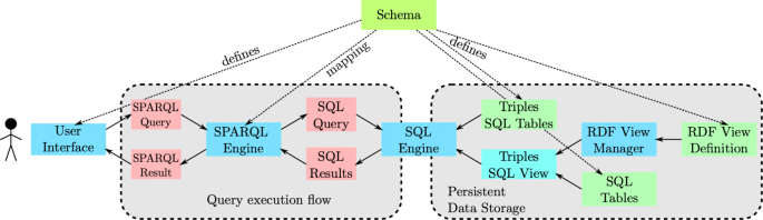
Example of a SPARQL Query execution. Software components are shown in blue (i.e. User Interface, SPARQL Engine, SQL Engine and RDF View Manager). The data is shown in green (i.e. Triples SQL Tables, Triples SQL View, SQL Tables and RDF View Definition). The SQL and SPARQL Queries and their results are visualized in red. The database schema defines the storage structure of RDF ⊕ Documents, SQL Tables, and the RDF View Definition used to map arbitrary SQL tables to a set of RDF Triples. The schema also defines the structure of queries used to access the data and the conversion from SPARQL to SQL for the mapping between RDF Graph reference and actual SQL Tables and Views
-
SPARQL Engine - The SPARQL Engine converts the SPARQL Query into a corresponding SQL Query. After the query is executed it also converts the result back into an SPARQL Result.
-
SQL Engine (in this case PostgreSQL) - The SQL Engine is responsible for execution of the SQL Query over the selected RDF Graphs (either stored as SQL tables or accessible through an SQL View).
-
RDF View Manager - The RDF View manager then generates an SQL View based on an RDF View definition, i.e. mapping any SQL Tables to an RDF Graph representation.

When a user selects an area of interest in the User Interface, together with a data type of interest, an SPARQL Query is generated and sent to the SPARQL Engine which converts it into an SQL Query over a virtual table with three fields (subject, predicate, object). This virtual table is the union of a set of RDF Graphs (represented as SQL Tables) and a set of RDF Views (mapping between any SQL Tables and an RDF Graph representation). The RDF Views are generated by the RDF View Manager based on an RDF View Definition and an existing set of SQL Tables. Once the SQL Query has been executed, the results are returned to the SPARQL Engine which generates an SPARQL Result which can be visualised in the User Interface.
Schemas are used by the user interface to define the structure of allowed queries, and during execution by the SPARQL Engine to understand the mapping between RDF Graph URLs and the SQL Table or View, where the RDF data can be queried. For details and examples, see Appendix B Additional sPARQL queries of interest.
In the case study, we showed how to collect information through specification of geographic regions or boundaries. This idea can be leveraged in many different ways. For example, suppose an operator or human rescuer is interested in knowledge about surrounding building structures and would like 3D models of existing building structures. An example query, given in Listing 2, shows how this can be done using the data from the case study missions.
In the case study, LIDAR sensor data and intermediate point cloud data were collected by several UAV agents and stored distributively in their respective SCModules. Additionally, a human ground operator acquired some of this data through SPARQL queries and the use of the Data Exchange Protocol. During this process, raw sensor data was stored in the agent’s respective PostgreSQL databases in table form (see Appendix A Representation of data structures in SCModules). Using the RDF View system, this data can be accessed using SPARQL as a high-level query language.
In the following, the prefixes before the URLs will be used for defining the RDF View and SPARQL query used to retrieve 3D models of building structures in a geographical region:
-
askcore_pointclouds: http://askco.re/pointclouds#. This prefix is used for definitions related to point clouds. askcore_pointclouds:patch is the predicate that specifies the raw data of the point. askcore_pointclouds:intersection is a function that computes the intersection of a point cloud with a geometric object. askcore_pointclouds:union computes the union of a set of point clouds.
-
askcore_types: http://askco.re/types#. This prefix designates data types stored in the database, such as askcore_pointclouds:pointclouds.
-
askcore_graphs: http://askco.re/graphs#. This prefix designates the RDF Graphs used in the system. askcore_graphs:pointclouds_view is an RDF View which enables one to query point clouds stored in SQL Tables using SPARQL queries.
-
geo: http://www.opengis.net/ont/geosparql#. This is the standard prefix for GeoSPARQL [29], which enhances RDF and SPARQL with features specific to GIS.
-
geof: http://www.opengis.net/def/function/geosparql/#. This is the standard prefix for functions defined by GeoSPARQL.
An RDF View mapping the SQL table for point clouds to an RDF Triple representation using Sparqlify [23] is shown in Listing 1.

The SPARQL query presented in Listing 2 is then used to retrieve 3D point clouds corresponding to the 2D footprints of buildings in the regions of interest from the case study.

The result of the execution of the SPARQL query is shown in Fig. 23. For additional details about sensor data representations used and examples of other queries, see Appendices A Representation of data structures in SCModules and B Additional sPARQL queries of interest.

Results of querying the operator’s database for a point cloud representation of an existing set of buildings based on the point clouds acquired in Section 7.2. Note that some requested buildings have no point clouds in the team KDB repositories
8 Related work
The HFKN Framework envisioned is unique in its approach, but does take inspiration from some of the challenges and problems in related topic areas. In this section, we consider some of this work most relevant to the HFKN Framework.
Distributed Knowledge and Multi-Agent Systems Multi-Agent Systems (MAS) [30, 31] have direct relevance to the HFKN Framework since we view each robotic system as an agent with capabilities to plan and reason. In MAS, the topics of distributed and common knowledge are central to logical approaches to multi-agent problem solving and inference [32]. In the HFKN Framework, each agent has its own local knowledge in the form of RDF Documents/Graphs that are distributed across agents. The multi-agent system consisting of a team of agents has common knowledge in the form of the shared, synchronized RDF Documents/Graphs. Collections of RDF triples (RDF Documents) can be viewed logically [33–35]. This being the case, certain kinds of querying mechanisms, analogous to deductive databases [36], can be viewed as doing logical inference. SPARQL-DL [37] is an interesting example of this.
Communication among agents is also an important topic in MAS. A common approach for communication in MAS is to use an implementation of the Agent Communication Language (ACL) such as FIPA ACL [38]. ACL contains mechanisms for agents to query other agents and transfer beliefs between them. This provides an infrastructural mechanism for belief transfer but also requires a semantics for beliefs such as that used in the BDI approach [39, 40]. It should be noted that the Delegation Framework and its integration with the HFKN Framework, does use ACL and speech acts for general communication between agents and that general communication mechanism carries over for use with SCModules.
One of the challenges with such multi-agent systems that is related to belief transfer is for agents to determine what agents to ask for certain information required during a mission. Sending a broadcast is not always practical, since for large numbers of agents, this approach could degrade the available bandwidth of the communication network. A potential solution involves using matchmaker agents [41] that hold information about which agents can answer questions. Our approach is much different because each agent’s public/shared information is synchronized, so the collective knowledge from a team is accessible directly to each agent. Consequently, each agent can then internally query such information. Raw sensor data is indirectly accessible through metadata and dataset transfer protocols, but an agent can still directly query a dataset’s metadata to acquire useful knowledge.
In Cloud Robotics [42], the functionalities of robotic systems are usually enhanced using cloud-based solutions. They can be used to offload computations or for the exchange of knowledge through centralized databases. The work presented in this paper is capable of handling scenarios where the communication is unreliable or unavailable, for which it is impractical to rely on distant servers, such as those implicit in the use of cloud-based approaches.
Distributed and Federated Database Systems The main challenge in Federated Database Systems (FDS) [43, 44] is to provide a unified query mechanism that hides data inconsistencies. This is often called the database integration problem [45]. The main challenges in Distributed Database systems [46–48] is the consistency problem where schema definitions and data should be consistent and equal across the different database instances.
Traditional database technology provides common techniques for storing data and querying data. For databases running on a single computer and using smaller amounts of data, data consistency is less of an issue. But this does not scale for large numbers of users and large amounts of data. This has led to the development of Distributed Database Management Systems (DDBMS) [48]. Homogeneous DDBMS are systems where the schema definitions and data should be consistent and equal across the different database instances. A common approach to solving this consistency problem is to use database replication [47], where a master has write permissions on a subset of the data, and when changes occur, they are propagated to the slaves. Homogeneous DDBMS also solve the problem of load balancing between servers. In the case of Big Data, when a single computer cannot store all of its data in memory, it is necessary to use a Heterogeneous DDBMS approach, such as Spanner [46] or Dynamo [49]. Here, the system controls which server stores which data depending on user needs and system requirements. In [46], the authors propose a dynamic system to lock tables so that only a single instance can write on a subset of the table schema. This approach is also capable of handling inaccuracies in the timestamping of transactions. In [49] the data is replicated across multiple hosts. Dynamo trades-off consistency for availability, where data is guaranteed to be eventually consistent, that is all updates reach all replicas eventually. Generally, these systems rely on a central server or policy for handling the spread and distribution of data. Their goal is to optimize the efficient accessibility of data by end-users and deal with load balancing between servers.
In Homogeneous and Heterogeneous DDBMS, the control over the availability and writing of data is left to the system. In Federated Database Systems (FDS), each database instance is autonomous, in the sense that there is no assumption as to the individual schema and the availability and location of where specific data resides. What is of particular focus is the development of a common query mechanism across heterogeneous databases. Such systems have to deal with many types of data inconsistencies, such as naming of concepts, precision, schema alignment, etc.
FDS attempts to provide unified query mechanisms that hide data inconsistencies in order to deal with the database integration problem [45]. A solution to the distributed mapping of integrated answers to queries was proposed in [44], where the system is required to be static, and each database instance must remain in the federation. A more dynamic approach was recently proposed in [43], where the FDS is implemented as a graph. When a query is executed, it is propagated along the graph and at each node the results are aggregated, correcting the inconsistencies incrementally.
The HFKN Framework shares some ideas from both DDBMS and FDS technologies. In the HFKN Framework, the SQL databases associated with each agent, is not intended to be shared, globally consistent or replicated across agents. These databases are heterogeneous by design. On the other hand, the schema for representing sensor data of any kind is common to all agents in the system. Even at the RDF Document level intended to maintain semantic representations and meta-information about datasets describing collected sensor data, the HFKN framework does not require complete consistency. A form of weak consistency is guaranteed as discussed in [20].
With FDS, the schema (i.e. structure of the data) and concepts (i.e. the meaning of the data) are the same for all agents. In the HFKN framework, each agent has full autonomous control of what kind of data it stores. Agents can join and leave the federation at any time. This is different from previous work [44] with FDS where an agent can leave a federation only after obtaining a permission. In our application scenarios, communication is assumed to be unreliable. Consequently, the approach proposed in this paper is designed to handle dynamic changes in the federation structure without any notice.
Like FDS, our approach does use a unified query mechanism, SPARQL (SPARQL Protocol and RDF Query Language) [21] for this collection of shared RDF Documents/Graphs, but also locally for internal agent queries of all its RDF Documents, shared and unshared. SPARQL was developed for querying information stored in RDF Graphs.
Semantic Web and Robotics Our choice of representation for information and knowledge, RDF Documents/Graphs, is inspired by Tim Berners-Lee’s vision of a Semantic Web [50–52], where web pages in the World Wide Web are annotated with representations of their semantic content in the form of collections of RDF Triples (RDF Documents) and ontologies and linked across the WWW. These information structures can be reasoned about using logical inference mechanisms such as those based on Description Logics [53], in addition to related powerful ontology inference mechanisms such as OWL [19, 53]. The modern equivalent of these ideas has resulted in standardization [16, 18, 19, 35] and the linked-data [54] research area of which knowledge graphs are a prime example. Many additional tools and technologies have been developed since the original idea of the Semantic Web was proposed and these are used in the backbone of many companies’ knowledge-intensive products.
More recently, there has been a trend toward leveraging Semantic Web ideas with robotics [6, 55–59]. Many existing ontologies are available and useful for describing robotic systems [60, 61] and sensing for robotics [57].
Several frameworks using Semantic Web technologies have been implemented on robotics systems. The OpenRobots Ontology (ORO) [55] presents a processing framework leveraging Semantic Web technologies to enhance communication between robots and humans. ORO makes use of a common sense ontology, an events system, a model of the cognitive state of other agents, and a long term memory. In [56], the authors present a method to connect low-level sensor data and high-level semantic information using RDF and an ontology for low-level information.
The HFKN Framework relies heavily on Semantic Web technologies. This choice is due in part to the conceptual fit between our ideas and these technologies and the wider availability of collective knowledge on the Internet provided in the form of ontologies and RDF Documents/Graphs, the latter often called knowledge graphs. Due to the similarities, these knowledge sources can be leveraged, integrated, and used to best advantage by the collaborative agents in the scenarios we focus on.
Many Semantic Robots frameworks [62, 63] have been developed with a focus on how to represent knowledge for heterogeneous systems, rather than how to exchange knowledge. One of the most mature frameworks combining Semantic Web technologies and robotics is KnowRob [64, 65], a knowledge processing framework for robotic agents. KnowRob supports reasoning over semantic information while taking into account planning processes. KnowRob needs to be used in conjunction with a knowledge base such as the Robot Scene Graph (RSGraph) [66, 67]. RSGraph is a framework for representing 3D information about a robot’s environment in a graph structure stored in the volatile memory of the robot. Work that combines RSGraph and KnowRob is presented in [68].
In the HFKN Framework, an agent’s SCModule stores information in its PostgreSQL database in the KDB. This architecture results in the information being stored on the hard drive whereas continually used information is cached in memory. The benefit of this is that the information is saved long term and is persistent even when a particular robot agent goes offline. The information is not duplicated but shared across the modules of a robot. However, there is additional overhead when accessing the information stored in the PostgreSQL database when compared to the in-memory solution used with RSGraph. Still, efficient caching minimizes this as an issue.
RSGraph has recently been extended with a synchronization mechanism in [67], which allows the distribution of RSGraph nodes across a team of agents. Since some of the information stored in RSGraph can be large (e.g. point clouds), the authors have implemented a QoS solution that checks the network’s quality and then downsamples the information relative to network congestion levels.
The HFKN framework deals with much more general forms of synchronisation then those provided in RSGraph. Additionally, only low bandwidth information is automatically exchanged between agents through synchronization. Large datasets (e.g. point clouds and images) are only transferred after an explicit request from an agent. This results in a by-need philosophy, where agent SCModules transfer full resolution information only when needed. Note that there is a throttling mechanism that controls data transfer bandwidth when using the data exchange protocol. This is, in fact, a form of QoS mechanism. One could envision combining these ideas with the QoS techniques used in RSGraph, but we save such issues for future work.
Applications with Mapping The topic of Distributed Simultaneous Localisation and Mapping (SLAM) has some relation to our applications of the HFKN Framework. One of the basic functionalities in any robotic platform is building a map of the environment. Many algorithms have been developed for a single robot [69, 70], which deal with the problem of fusing information coming from multiple sensors in a robot. Such algorithms have been extended to support fusion of sensor data from multiple robots. Earlier work involved considering a set of local maps connected in a global graph shared between robots [71]. This approach was superseded by introducing landmarks directly in global graphs [72]. However, such approaches require a central location for the fusion of the global map. A decentralized approach was proposed in [73]. The authors suggested using a version control system for the map, but this still required a lock when fusing part of the map distributed between platforms.
A practical application of building a common map by a group of robots is to solve the problem of exploration of a large environment [74]. Most of these approaches use either a centralized server or a global lock, while HFKN is a dynamically decentralized system. The lock is implicit in the synchronization algorithm. The approaches considered here are specific to solving the distributed fusion problem, whereas HFKN is a more general framework.
As mentioned earlier, the KDB is GIS (Geographic information systems)-like in concept since it stores low-level sensor data, intermediate information, and high-level semantic knowledge. Although the KDB architecture is not layered in the GIS sense, SPARQL queries about specific geographical regions return information about those regions at many different conceptual layers.
GIS systems can be used to store a wide range of vector information (points, lines, polygons, etc. [75]). They have also been extended to allow storage of 3D information such as point clouds [76] or point clouds augmented with semantic knowledge [77]. The latter is directly related to how the KDB can semantically label lower-level data geographically.
As the state of an operational environment is continuously evolving, it is natural to use remote sensors to update GIS [78]. In [79], a centralized GIS server is used to share rescue information, where autonomous robots push observations to the GIS server and where rescuers can then access that information. As discussed previously, the HFKN Framework collects data and knowledge dynamically via agents yet stores it in a distributed manner. The HFKN Framework uses a weak form of replicated centralization in that each agent shares metadata about other agent’s public data and knowledge. The synchronization process keeps this data and knowledge weakly consistent across agents. There is no centralized server or source of global information.
9 Conclusions
We have presented a general system architecture and framework, called the SymbiCloud HFKN Framework, for supporting dynamic, distributed situation awareness for heterogeneous teams of human/robotic agents. The system builds upon previous work using a delegation framework for dynamic task allocation for collaborative human/robotic systems that is also part of the general system architecture.
The major focus of the paper has been the description and specification of core system algorithms for supporting distributed data and knowledge collection and the storage, synchronization, aggregation and transfer of such data and knowledge among teams of collaborating agents. In this case, our teams have consisted of humans and UAVs.
Major effort has been placed on incorporating resiliency into the algorithms and the resulting engineered system to deal with difficult problems associated with unreliable communication among agents, out-of-range issues, agents entering and leaving mission environments, in addition to the heterogeneity of both the data collected and the systems used to collect such data. Currently, the HFKN framework makes a strong assumption that its agents are operating in secure environments, where all agents are considered trustworthy and cooperative. In future work, plans include investigating different aspects related to the security and trustworthiness of data, for instance, by using the cryptographic signatures already present in the RGS ⊕ infrastructure.
A seamless unification of data, information and knowledge has been achieved through the use of Semantic Web technologies as a basis for structuring and querying collected sensor data, meta-information about such sensor data, and post-processed knowledge in the form of RDF (knowledge) graphs. The system can easily be extended with additional ontologies other than those described in the paper to provide richer semantic decision support.
Although the focus of this paper has been on the dynamic collection of sensor data for constructing 3D maps and limited object representations such as people and building structures, the system is general in nature and any type of semantic information that can be modeled using RDF (knowledge) Graphs could be collected, represented, processed and queried in a similar manner.
Empirical experimentation in simulation has been performed showing the speed and scalability of the proposed system and algorithms. Additionally, field experimentation has been done using emergency rescue scenarios with teams of UAVs and humans to show the viability of the ideas in the engineered HFKN system.
10 Appendix
10.1 A Representation of data structures in SCModules
In Section 7.3, Fig. 22, we provided an overview of different ways to query an SCModule using SPARQL. In this appendix, additional details are provided concerning some of the basics Schemas and RDF Views used in the HFKN Framework, together with a selected set of SQL table representations.
Triples table An RDF Graph consists of triples (subject, predicate, object) which are stored in an SQL table with three fields presented in Table 2. The SQL table fields correspond directly to the components of a triple (see also Fig. 8). The type of the object field provides a means to efficiently store various data types such as integers, strings, lists, images, point clouds, etc.
RDF Document An RDF Document is stored using three tables:
-
A triples tables corresponding to a version of the RDF Graph, which is available for answering queries or performing change operations (see Table 2).
-
A revision table containing the metadata associated with each RDF Revision (see Table 3).
Table 3 Fields of the RDF revision SQL table -
A delta table containing the RDF deltas (see Table 4).
Table 4 Fields of the RDF delta SQL table
The database also contains metadata about the RDF Document:
-
The revision hash of the current instance.
-
The URI used to identify the RDF Graph.
RDF Delta
Deltas are encoded using a subset of SPARQL Update query [21]. Only two queries are allowed, i.e.  and
and  . This is because these are the only two types of queries to unambiguously identify the inserted and removed triples.
RDF Blank NodesFootnote 5 are encoded using the skolemization process [80], i.e. blank node are replaced by a unique URI assigned by the KDB Manager.
An example of an RDF Delta with one triple being added and one removed is encoded as an SPARQL Update query in the following way:

Position and Transformation tables
Internally our robots use the ROS TF library [81] for representing coordinate frames of all the agents. TF allows for keeping track of all transformations between different components of a robot (and between robots) represented as a tree. Each node in the tree corresponds to a frame and includes the rotation and translation between that frame and its parent (see Fig. 24). The root of the tree is usually the origin of the world.

Example of a transformation tree for a single agent. The origin of the world is represented by the frame world and the root frame for the agent is body_link
The definition of the origin of the world is agent-specific and can be different for all agents. Therefore in SCModule, we cut the tree at the main reference frame of each agent and record the corresponding geoposes as different entries in the Position table. This allows for maintaining a global coordinate frame for all agents in the system. For example, in Fig. 24, only the base_link and all its children (pan_tilt, camera, IMU) are saved in the Transformation table (top of Table 5) and the geopose (latitude, longitude, altitude and orientation) of the base_link is saved in the Position table (bottom of Table 5).
Images
Image data is stored in two tables: CameraFrame and CameraInfo presented in Table 6. The former contains basic information about the parameters of an image such as the time of acquisition, its size, encoding type, etc. The most bandwidth-intensive part is the data (i.e. pixel values). The latter contains calibration information of the camera sensor, such as the matrix of camera intrinsic parameters K as well as the lens distortion parameters D.
Point clouds
Sensor data representing point clouds is stored in one table presented in Table 7. Point cloud data typically consists of many measurements, and storing them as individual records in a database is inefficient. Instead, we use data representation proposed in [84]. The base type PcPoint is used to encode a single point LIDAR measurement. A collection of those points is then grouped in a complex type PcPatch which is stored as a record in the database reducing the total number of entries. The RDF View defining the mapping between the table and corresponding RDF Triples used for querying of point cloud data is shown in Fig. 25.

The RDF View (http://example.org/point_clouds) definition for point clouds
LIDAR data
LIDAR data is stored in two tables: LidarFrame and LidarConfig presented in Table 8. The former contains information about the time of acquisition, a pointer to the sensor’s configuration, and the actual LIDAR readings in the form of ranges and return intensities. The latter contains information about the sensor configuration used during the data collection. Most importantly, angular and range resolutions are specified. The RDF View definitions for the mapping between the SQL Tables and a set of triples that can be queried with SPARQL are shown in Fig. 26.

The RDF View definition for LIDAR Frames (http://example.org/lidar_frames, top) and the associated configuration of the sensor (http://example.org/lidar_config, bottom)
10.2 B Additional sPARQL queries of interest
Based on the specifications in Appendix A Representation of data structures in SCModules, this appendix provides additional examples of sensor-related SPARQL queries and their use in acquiring object data about building structures.
Query for the range data of a LIDAR sensor
The following query returns a set of ranges from the specified dataset, i.e.  from the dataset
  :
:

The first part of the query selects the  that belongs to the dataset
  :
:

The second part of the query retrieves the  data:
data:

Query for acquiring a list of buildings and their 3D models
This is an example of a query to access a list of buildings  and their corresponding 3D models
  :
:

The first part of the query lists all buildings. Their 2D footprints are stored in  and their names in
  :
:

The second part of the query lists all the point clouds  whose footprints
  were obtained by projecting all the points on a 2D plane intersecting with a specified building footprint
  :
:

Finally, the point clouds are combined to give a single result for each building with:

The  function takes a set of 3D point clouds and combines them into a single one. The
  function takes a point cloud and a 2D footprint and output a point cloud for which each point is inside the footprint.
Availability of data and materials
No data is available.
Code Availability
No custom code has been submitted.
Notes
ROS is an acronym for the Robot Operating System, a middleware framework for robotics. For more information, see https://www.ros.org. Both ROS and ROS2 are currently used in the framework because ROS2 has better communication support for multi-agent systems. At a later date, full transition to ROS2 will be made.
The sensor data based datasets considered here are different from RDF Datasets.
A Scan mission is a generic type of mission in which agents collect data with their sensors, such as camera or LIDAR, over an area.
Blank nodes can be used to identify an element of an RDF Triple without providing an explicit URI
References
P. J. Denning, Hastily formed networks. Commun. ACM. 49(4), 15–20 (2006). https://doi.org/10.1145/1121949.1121966.
P. Doherty, J. Kvarnström, P. Rudol, M. Wzorek, G. Conte, C. Berger, T. Hinzmann, T. Stastny, in PRIMA 2016: Principles and Practice of Multi-Agent Systems, Lecture Notes in Computer Science, vol. 9862, ed. by M. Baldoni, A. K. Chopra, T. C. Son, K. Hirayama, and P. Torroni. A Collaborative Framework for 3D Mapping using Unmanned Aerial Vehicles (Springer Publishing CompanyPhuket, 2016), pp. 110–130. https://doi.org/10.1007/978-3-319-44832-9_7.
E. Horvitz, Mixed-initiative interaction (IEEE Intelligent Systems, 1999). https://doi.org/10.1109/5254.796083. https://www.microsoft.com/en-us/research/publication/mixed-initiative-interaction/.
J. Ji, P. Fazli, S. Liu, T. Pereira, D. Lu, J. Liu, M. Veloso, X. Chen, in Proceedings of ICSR’16, the International Conference on Social Robots. Help me! sharing of instructions between remote and heterogeneous robots (Limassol, 2016), pp. 786–795. https://doi.org/10.1007/978-3-319-47437-3_77.
J. Kvarnström, in Proceedings of the 21st International Conference on Automated Planning and Scheduling (ICAPS), ed. by F. Bacchus, C. Domshlak, S. Edelkamp, and M. Helmert. Planning for Loosely Coupled Agents Using Partial Order Forward-Chaining (AAAI PressFreiburg, 2011), pp. 138–145.
S. Lemaignan, M. Warnier, E. Sisbot, A. Clodic, R. Alami, Artificial cognition for social human-robot interaction: An implementation. Artificial Intelligence. 247: (2016). https://doi.org/10.1016/j.artint.2016.07.002.
L. Luo, N. Chakraborty, K. Sycara, Distributed algorithms for multirobot task assignment with task deadline constraints. IEEE Trans. Autom. Sci. Eng. Spec. Issue Networked Coop. Auton. Syst.12(3), 876–888 (2015). https://doi.org/10.1109/TASE.2015.2438032.
M. M. Veloso, The Increasingly Fascinating Opportunity for Human-Robot Interaction: The CoBot Mobile Service Robots. ACM Trans. Hum.-Robot Interact. (2018). https://doi.org/10.1145/3209541.
P. Doherty, F. Heintz, J. Kvarnström, High-level mission specification and planning for collaborative unmanned aircraft systems using delegation. Unmanned Syst.1(1), 75–119 (2013). https://doi.org/10.1142/S2301385013500052.
P. Doherty, J. Kvarnström, A. Szalas, in Proceedings of the 13th International Conference on Principles of Knowledge Representation and Reasoning (KR). Temporal composite actions with constraints (AAAI PressKolkata, 2012), pp. 478–488. https://doi.org/10.1007/978-3-642-25920-3_4.
P. Doherty, J. Kvarnstrom, M. Wzorek, P. Rudol, F. Heintz, G. Conte, in Handbook of Unmanned Aerial Vehicles, ed. by K. P. Valavanis, G. J. Vachtsevanos. HDRC3: A distributed hybrid deliberative/reactive architecture for unmanned aircraft systems (Springer NetherlandsDordrecht, 2015), pp. 849–952. https://doi.org/10.1007/978-90-481-9707-1_118.
M. Quigley, B. Gerkey, K. Conley, J. Faust, T. Foote, J. Leibs, E. Berger, R. Wheeler, A. Ng, in Proc. of the IEEE Intl. Conf. on Robotics and Automation (ICRA) Workshop on Open Source Robotics. Kobe, (2009).
P. Doherty, J. J. C. Meyer, in The Goals of Cognition: Essays in honour of Cristiano Castelfranchi, ed. by F. Paglieri, L. Tummolini, R. Falcone, and M. Miceli. On the logic of delegation - relating theory and practice (College Publications, 2012), pp. 467–496.
T. Hinzmann, T. Stastny, G. Conte, P. Doherty, P. Rudol, M. Wzorek, E. Galceran, R. Siegwart, I. Gilitschenski, in International Symposium on Experimental Robotics. Collaborative 3D reconstruction using heterogeneous uavs: System and experiments (Tokyo, 2016), pp. 43–56. https://doi.org/10.1007/978-3-319-50115-4_5.
P. Doherty, F. Heintz, D. Landén, in Proceedings of the International conference on principles and practice of multi-agent systems (PRIMA), Lecture Notes in Computer Science, vol. 7057. A distributed task specification language for mixed-initiative delegation (Kuching, 2012), pp. 42–57. https://doi.org/10.1007/978-3-642-25920-3_4.
F. Gandon, G. Schreiber, RDF 1.1 xml syntax. recommendation (World Wide Web Consortium (W3C), Cambridge, 2014). https://www.w3.org/TR/rdf-syntax-grammar/.
M. Duerst, M. Suignard, RFC 3987: Internationalized Resource Identifiers (IRIs). RFC 3987 (Proposed Standard) (2005). http://www.ietf.org/rfc/rfc3987.txt.
D. Brickley, R. V. Guha, B. McBride, RDF schema 1.1. recommendation (World Wide Web Consortium (W3C), Cambridge, 2014).
D. L. McGuinness, F. Van Harmelen, et al., OWL 2 web ontology language document overview, (second edition). recommendation (World Wide Web Consortium (W3C), Cambridge, 2012). https://www.w3.org/TR/owl2-overview/.
C. Berger, P. Doherty, P. Rudol, M. Wzorek, Hastily formed knowledge networks and distributed situation awareness for collaborative robotics, (2021). Preprint at https://arxiv.org/abs/2103.14078.
A. Seaborne, G. Manjunath, C. Bizer, J. Breslin, S. Das, I. Davis, S. Harris, K. Idehen, O. Corby, K. Kjernsmo, et al., SPARQL/Update: A language for updating RDF graphs. Tech. rep. (World Wide Web (W3C), Cambridge, 2008).
S. S. Sahoo, W. Halb, S. Hellmann, K. Idehen, T. Thibodeau, S. Auer, J. Sequeda, A. Ezzat, A survey of current approaches for mapping of relational databases to RDF. Tech. rep., W3C RDB2RDF Incubator Group Report, (2009).
C. Stadler, J. Unbehauen, P. Westphal, M. A. Sherif, J. Lehmann, in Proceedings of the 8th Workshop on Linked Data on the Web (LDOW). Simplified RDB2RDF mapping (Rio de Janeiro, 2015).
C. Bizer, A. Schultz, The berlin SPARQL benchmark. Int. J. Semantic Web Inf. Syst. (IJSWIS). 5(2), 1–24 (2009). https://doi.org/10.4018/978-1-60960-593-3.ch004.
M. Fowler, Patterns of Enterprise Application Architecture (Addison-Wesley, San Francisco, 2012).
C. Schlenoff, E. Prestes, R. Madhavan, P. Goncalves, H. Li, S. Balakirsky, T. Kramer, E. Migueláñez, in 2012 IEEE/RSJ International Conference on Intelligent Robots and Systems. An ieee standard ontology for robotics and automation (Vilamoura, 2012), pp. 1337–1342. https://doi.org/10.1109/IROS.2012.6385518.
M. Wylot, M. Hauswirth, P. Cudré-Mauroux, S. Sakr, Rdf data storage and query processing schemes: A survey. ACM Comput. Surv.51(4) (2018). https://doi.org/10.1145/3177850.
A. Seaborne, A. Polleres, L. Feigenbaum, G. T. Williams, SPARQL 1.1 federated query. recommendation, World Wide Web Consortium (W3C), (Cambridge, 2013). https://www.w3.org/TR/sparql11-federated-query/.
R. Battle, D. Kolas, Enabling the geospatial semantic web with parliament and geosparql. Semantic Web. 3(4), 355–370 (2012). https://doi.org/10.3233/sw-2012-0065.
Shoham Yoav, K. Leyton-Brown, Multiagent Systems - Algorthmic, Game-Theoretic, and Logical Foundations (Cambridge University Press, Cambridge, 2009).
M. Wooldridge, An Introduction to MultiAgent Systems, 2nd edn (Wiley, Hoboken, 2009).
R. Fagin, J. Y. Halpern, Y. Moses, M. Y. Vardi, Reasoning about Knowledge (MIT Press, Cambridge, 1995).
J. de Bruijn, S. Heymans, in 18th International Conference on Database and Expert Systems Applications (DEXA 2007). RDF and logic: Reasoning and extension (IEEERegensburg, 2007), pp. 460–464. https://doi.org/10.1109/dexa.2007.8.
J. de Bruijn, S. Heymans, Logical foundations of rdf(s) with datatypes. J. Artif. Intell. Res.38:, 535–569 (2010). https://doi.org/10.1613/jair.3088.
P. Hayes, P. F. Patel-Schneider, RDF semantics. recommendation (World Wide Web Consortium (W3C), Cambridge, 2004). https://www.w3.org/TR/rdf11-mt/.
S. Greco, C. Molinaro, Datalog and Logic Databases. Synthesis Lectures on Data Management (Morgan & Claypool, San Rafael, 2016). https://doi.org/10.2200/s00648ed1v01y201505dtm041.
E. Sirin, B. Parsia, in Proceedings of the 3rd International Workshop on OWL: Experiences and Directions. SPARQL-DL: SPARQL query for OWL DL (Innsbruck, 2007).
S. Poslad, Specifying protocols for multi-agent systems interaction. ACM Trans. Auton. Adaptive Syst. (TAAS). 2(4) (2007). https://doi.org/10.1145/1293731.1293735.
M. Bratman, Intention, Plans, and Practical Reason (Harvard University Press, Cambridge, 1987). https://doi.org/10.2307/2215590.
A. S. Rao, M. P. Georgeff, in Proceedings of the 2nd International Conference on Principles of Knowledge Representation and Reasoning (KR’91), ed. by R. F. J. Allen, E. Sandewall. Modeling rational agents within a BDI-architecture (Morgan KaufmanCambridge, 1991), pp. 473–484. https://doi.org/10.5555/3087158.3087205.
J. R. Chen, S. R. Wolfe, S. D. Wragg, in Proceedings of the Ninth International Conference on Information and Knowledge Management. A distributed multi-agent system for collaborative information management and sharing (McLean, 2000), pp. 382–388. https://doi.org/10.1145/354756.354844.
B. Kehoe, S. Patil, P. Abbeel, K. Goldberg, A survey of research on cloud robotics and automation. IEEE Trans. Autom. Sci. Eng.12(2), 398–409 (2015). https://doi.org/10.1109/TASE.2014.2376492.
G. Bent, P. Dantressangle, D. Vyvyan, A. Mowshowitz, V. Mitsou, in Proceedings of the 2nd Annual Conference of the International Technology Alliance. A dynamic distributed federated database (London, 2008).
A. P. Sheth, J. A. Larson, Federated database systems for managing distributed, heterogeneous, and autonomous databases. ACM Comput. Surv. (CSUR). 22(3), 183–236 (1990). https://doi.org/10.1145/96602.96604.
C. Parent, S. Spaccapietra, Issues and approaches of database integration. Commun. ACM. 41(5es), 166–178 (1998). https://doi.org/10.1145/276404.276408.
J. C. Corbett, J. Dean, M. Epstein, A. Fikes, C. Frost, J. J. Furman, S. Ghemawat, A. Gubarev, C. Heiser, P. Hochschild, W. Hsieh, S. Kanthak, E. Kogan, H. Li, A. Lloyd, S. Melnik, D. Mwaura, D. Nagle, S. Quinlan, R. Rao, L. Rolig, Y. Saito, M. Szymaniak, C. Taylor, R. Wang, D. Woodford, Spanner: Google’s globally distributed database. ACM Trans. Comput. Syst.31(3) (2013). https://doi.org/10.1145/2491245.
S. A. Moiz, P. Sailaja, G. Venkataswamy, S. N. Pal, Database replication: A survey of open source and commercial tools. Int. J. Comput. Appl.13(6), 1–8 (2011). https://doi.org/10.5120/1788-2469.
M. T. Özsu, P. Valduriez, Principles of Distributed Database Systems (Springer, Berlin, 2020). https://doi.org/10.1007/978-3-030-26253-2.
G. DeCandia, D. Hastorun, M. Jampani, G. Kakulapati, A. Lakshman, A. Pilchin, S. Sivasubramanian, P. Vosshall, W. Vogels, Dynamo: Amazon’s highly available key-value store. ACM SIGOPS Oper. Syst. Rev.41(6), 205–220 (2007). https://doi.org/10.1145/1323293.1294281.
D. Allemang, J. Hendler, F. Gandon, Semantic Web for the Working Ontologist: Effective Modeling for Linked Data, RDFS, and OWL, 3edn. (Association for Computing Machinery, New York, 2020). https://doi.org/10.1145/3382097.
T. Berners-Lee, J. Hendler, O. Lassila, The semantic web. Sci. Am.284(5), 34–43 (2001). http://www.jstor.org/stable/26059207.
J. Hendler, Agents and the semantic web. IEEE Intell. Syst.16(2), 30–37 (2001). https://doi.org/10.1109/5254.920597. http://dx.doi.org/10.1109/5254.920597.
F. Baader, D. Calvanese, D. Mcguinness, D. Nardi, P. Patel-Schneider, The Description Logic Handbook: Theory, Implementation, and Applications, 2edn. (Cambridge University Press, 2007). https://doi.org/10.1017/CBO9780511711787.
D. Wood, M. Zaidman, L. Ruth, M. Hausenblas, Linked Data: Structured Data on the Web (Manning Publications, Shelter Island, 2014).
S. Lemaignan, R. Ros, L. Mösenlechner, R. Alami, M. Beetz, in IEEE/RSJ International Conference on Intelligent Robots and Systems (IROS). Oro, a knowledge management platform for cognitive architectures in robotics (Taipei, 2010), pp. 3548–3553. https://doi.org/10.1109/IROS.2010.5649547.
G. H. Lim, I. H. Suh, H. Suh, Ontology-based unified robot knowledge for service robots in indoor environments. IEEE Trans. Syst. Man Cybern. Syst. Hum.41(3), 492–509 (2011). https://doi.org/10.1109/TSMCA.2010.2076404.
H. Neuhaus, M. Compton, in AGILE workshop on challenges in geospatial data harmonisation. The semantic sensor network ontology (HannoverGermany, 2009), pp. 1–33.
J. Persson, A. Gallois, A. Bjoerkelund, L. Hafdell, M. Haage, J. Malec, K. Nilsson, P. Nugues, in International Symposium on Robotics (ISR). A knowledge integration framework for robotics (Munich, 2010), pp. 1–8.
M. Stenmark, J. Malec, K. Nilsson, A. Robertsson, On distributed knowledge bases for robotized small-batch assembly. IEEE Trans. Autom. Sci. Eng.12(2), 519–528 (2015). https://doi.org/10.1109/TASE.2015.2408264.
J. L. Carbonera, S. R. Fiorini, E. Prestes, V. A. M. Jorge, M. Abel, R. Madhavan, A. Locoro, P. Gonçalves, T. Haidegger, M. E. Barreto, C. Schlenoff, in Proceedings of the IEEE/RSJ International Conference on Intelligent Robots and Systems (IROS). Defining positioning in a core ontology for robotics (Tokyo, 2013), pp. 1867–1872. https://doi.org/10.1109/IROS.2013.6696603.
C. Schlenoff, T. Hong, C. Liu, R. Eastman, S. Foufou, in Proceedings of the IEEE International Symposium on Robotic and Sensors Environments (ROSE). A literature review of sensor ontologies for manufacturing applications, (2013), pp. 96–101. https://doi.org/10.1109/ROSE.2013.6698425.
A. K. Bozcuoglu, G. Kazhoyan, Y. Furuta, S. Stelter, M. Beetz, K. Okada, M. Inaba, The exchange of knowledge using cloud robotics. Robot. Autom. Lett.3(2), 1072–1079 (2018). https://doi.org/10.1109/LRA.2018.2794626.
M. Waibel, M. Beetz, R. D’Andrea, R. Janssen, M. Tenorth, J. Civera, J. Elfring, D. Gálvez-López, K. Häussermann, J. Montiel, A. Perzylo, B. Schießle, O. Zweigle, R. van de Molengraft, RoboEarth - A World Wide Web for Robots. Robot. Autom. Mag.18(2), 69–82 (2011).
M. Beetz, D. Beßler, A. Haidu, M. Pomarlan, A. Bozcuoglu, G. Bartels, in 2018 IEEE International Conference on Robotics and Automation (ICRA). Know rob 2.0 — a 2nd generation knowledge processing framework for cognition-enabled robotic agents (Brisbane, 2018), pp. 512–519. https://doi.org/10.1109/ICRA.2018.8460964.
M. Tenorth, M. Beetz, Representations for robot knowledge in the knowrob framework. Artif. Intell. (2015). https://doi.org/10.1016/j.artint.2015.05.010.
S. Blumenthal, H. Bruyninckx, W. Nowak, E. Prassler, in 2013 IEEE International Conference on Robotics and Automation (ICRA). A scene graph based shared 3D world model for robotic applications (Karlsruhe, 2013), pp. 453–460. https://doi.org/10.1109/icra.2013.6630614.
S. Blumenthal, N. Hochgeschwender, E. Prassler, H. Voos, H. Bruyninckx, in 2015 IEEE/RSJ International Conference on Intelligent Robots and Systems (IROS). An approach for a distributed world model with QoS-based perception algorithm adaptation (Hamburg, p. 2015. https://doi.org/10.1109/iros.2015.7353612.
F. Yazdani, S. Blumenthal, N. Huebel, A. K. Bozcuoglu, M. Beetz, H. Bruyninckx, Query-based integration of heterogeneous knowledge bases for search and rescue tasks. Robot. Autom. Mag.117:, 80–91 (2019). https://doi.org/10.1016/j.robot.2019.03.013. http://www.sciencedirect.com/science/article/pii/S0921889018303488.
T. Bailey, H. Durrant-Whyte, Simultaneous localization and mapping (SLAM): part II. IEEE Robot. Autom. Mag.13(3), 108–117 (2006). https://doi.org/10.1109/MRA.2006.1678144.
H. Durrant-Whyte, T. Bailey, Simultaneous localization and mapping: part I. IEEE Robot. Autom. Mag.13(2), 99–110 (2006). https://doi.org/10.1109/MRA.2006.1638022.
T. A. Vidal-Calleja, C. Berger, J. Solà, S. Lacroix, Large scale multiple robot visual mapping with heterogeneous landmarks in semi-structured terrain. Robot. Auton. Syst.59:, 654–674 (2011). https://doi.org/10.1016/j.robot.2011.05.008.
A. Cunningham, K. M. Wurm, W. Burgard, F. Dellaert, in Proceedings of the IEEE International Conference on Robotics and Automation (ICRA). Fully distributed scalable smoothing and mapping with robust multi-robot data associationSaint Paul, 2012). https://doi.org/10.1109/ICRA.2012.6225356.
T. Cieslewski, S. Lynen, M. Dymczyk, R. Siegwart, in Proceedings of the IEEE International Conference on Robotics and Automation (ICRA). Map API - scalable decentralized map building for robots (Seattle, 2015), pp. 6241–6247. https://doi.org/10.1109/ICRA.2015.7140075.
R. Vincent, D. Fox, J. Ko, K. Konolige, B. Limketkai, B. Morisset, C. Ortiz, D. Schulz, B. Stewart, Distributed multirobot exploration, mapping, and task allocation. Ann. Math. Artif. Intell. (2008). https://doi.org/10.1007/s10472-009-9124-y.
A. B. Cox, F. Gifford, An overview to geographic information systems. J. Acad. Librariansh.23(6), 449–461 (1997). https://doi.org/10.1016/S0099-1333(97)90169-5.
R. Cura, J. Perret, N. Paparoditis, Point cloud server (PCS) : point clouds IN-base management and processing. ISPRS Ann. Photogramm. Remote. Sens. Spat. Inf. Sci.II-3/W5:, 531–539 (2015). https://doi.org/10.5194/isprsannals-ii-3-w5-531-2015. https://doi.org/10.5194%2Fisprsannals-ii-3-w5-531-2015.
F. Poux, P. Hallot, R. Neuville, R. Billen, in 3D Geoinfo Conference. Model for semantically rich point cloud data (Melbourne, 2017). https://doi.org/10.5194/isprs-annals-iv-4-w5-107-2017.
R. G. Congalton, Remote sensing and geographic information system data integration: error sources and research issues. Photogramm. Eng. Remote Sens.57(6), 677–687 (1991).
J. I. Meguro, K. Ishikawa, T. Hashizume, J. Takiguchi, I. Noda, M. Hatayama, in Proceedings of IEEE/RSJ International Conference on Intelligent Robots and Systems (IROS). Disaster information integration into geographic information system using rescue robots (Beijing, 2006). https://doi.org/10.1109/IROS.2006.281636.
A. Mallea, M. Arenas, A. Hogan, A. Polleres, in International semantic web conference. On blank nodes (SpringerBonn, 2011), pp. 421–437. https://doi.org/10.1007/978-3-642-25073-6_27.
T. Foote, in 2013 IEEE Conference on Technologies for Practical Robot Applications (TePRA). tf: The transform library (Woburn, 2013), pp. 1–6. https://doi.org/10.1109/TePRA.2013.6556373.
M. M. Macomber, World geodetic system 1984. Tech. rep. (Defense Mapping Agency Washington DC, Fort Belvoir, 1984). https://doi.org/10.21236/ada147409.
R. S. Williamson, R. Rapp, The development of the joint nasa gsfc and the national imagery and mapping agency (nima) geopotential model egm96. Tech. rep. (Goddard Space Flight Center, Greenbelt, 1998).
P. Ramsey, in FOSS4G. Lidar in postgresql with pointcloud (Nottingham, 2013).
Funding
This work has been supported by the ELLIIT Network Organization for Information and Communication Technology, Sweden (Project B09) and the Swedish Foundation for Strategic Research SSF (Smart Systems Project RIT15-0097). The first author is also supported by an RExperts Program Grant 2020A1313030098 from the Guangdong Department of Science and Technology, China in addition to a Sichuan Province International Science and Technology Innovation Cooperation Project Grant 2020YFH0160.
Author information
Authors and Affiliations
Contributions
Doherty contributed with the overview concept and framework for Hastily Formed Knowledge Networks and wrote a large portion of the article. Berger contributed to the conceptualization of the KDB manager, datasets and RDF synchronization in addition to developing the main prototype software architecture for HFKNS. Wzorek and Rudol contributed to iterations on all ideas and were responsible for field robotics experimentation. The latter three also contributed equally to the writing of the article. The authors read and approved the final manuscript.
Corresponding author
Ethics declarations
Competing interests
The authors declare that they have no known competing financial interests or personal relationships that could have appeared to influence the work reported in this paper.
Additional information
Publisher’s Note
Springer Nature remains neutral with regard to jurisdictional claims in published maps and institutional affiliations.
Rights and permissions
Open Access This article is licensed under a Creative Commons Attribution 4.0 International License, which permits use, sharing, adaptation, distribution and reproduction in any medium or format, as long as you give appropriate credit to the original author(s) and the source, provide a link to the Creative Commons licence, and indicate if changes were made. The images or other third party material in this article are included in the article’s Creative Commons licence, unless indicated otherwise in a credit line to the material. If material is not included in the article’s Creative Commons licence and your intended use is not permitted by statutory regulation or exceeds the permitted use, you will need to obtain permission directly from the copyright holder. To view a copy of this licence, visit http://creativecommons.org/licenses/by/4.0/.
About this article

Cite this article
Doherty, P., Berger, C., Rudol, P. et al. Hastily formed knowledge networks and distributed situation awareness for collaborative robotics. Auton. Intell. Syst. 1, 16 (2021). https://doi.org/10.1007/s43684-021-00016-w
Received:
Accepted:
Published:
DOI: https://doi.org/10.1007/s43684-021-00016-w