
Review of Fast Charging for Electrified Transport: Demand, Technology, Systems, and Planning


1
School of Engineering, University of Waikato, Hamilton 3216, New Zealand
2
School of Engineering, Macquarie University, Sydney, NSW 2109, Australia
*
Author to whom correspondence should be addressed.
Energies 2022, 15(4), 1276; https://doi.org/10.3390/en15041276
Submission received: 10 December 2021
/
Revised: 11 January 2022
/
Accepted: 28 January 2022
/
Published: 10 February 2022
(This article belongs to the Section E: Electric Vehicles)
Abstract
:As the number and range of electric vehicles in use increases, and the size of batteries in those vehicles increases, the demand for fast and ultra-fast charging infrastructure is also expected to increase. The growth in the fast charging infrastructure raises a number of challenges to be addressed; primarily, high peak loads and their impacts on the electricity network. This paper reviews fast and ultra-fast charging technology and systems from a number of perspectives, including the following: current and expected trends in fast charging demand; the particular temporal and spatial characteristics of electricity demand associated with fast charging; the devices and circuit technologies commonly used in fast chargers; the potential system impacts of fast charging on the electricity distribution network and methods for managing those impacts; methods for long-term planning of fast charging facilities; finally, expected future developments in fast charging technology and systems.
1. Introduction
The global transition to electrified transport is well underway, supported by the development and rollout of electric vehicles (EVs) and the necessary charging infrastructure [1]. The development and rollout of fast chargers, i.e., which can recharge an EV in approximately the same time as refilling an internal combustion engine (ICE) vehicle, is a prerequisite for many e-transport services (e.g., long distance transport, high utilization fleet vehicles), and facilitates the wider uptake of EVs [2,3]. Fast charging technology and systems will therefore be of increasing importance in the transition to electrified transport.
The purpose of this review is to provide a wholistic overview of developments in fast charging technologies and systems, from the expected demand and technology options, through system impacts and management, to network planning and potential future developments. Whilst several reviews have been published to date on specific topics relevant to fast charging—such as fast charger design [4,5,6,7,8,9], the impacts of fast charging on battery lifetime [10] and on the electricity network [11,12,13], and the various methods for limiting the negative impacts of fast charging [11,14,15,16], including integrated energy storage [17,18,19]—none have reviewed fast charging from a systems perspective, highlighting the interdependencies between the demand driving technical developments and the various approaches to planning and management of future charging infrastructures. Furthermore, fast charging technology and systems are rapidly developing areas; in the last decade, the number of research publications on fast and ultra-fast charging technology and applications has grown at an average rate of over 25% each year, and this trend shows no sign of slowing.
1.1. Definition and Standards
Electric vehicle charging rates are commonly referred to by the time required to charge the drive battery as either slow (>1 h, or <1 C per hour), fast (less than 1 h, or >1 C per hour), or ultra-fast (less than 20 min, or >3 C per hour); where C is the nominal coulometric capacity in ampere-hours, and the C-rate is the current in amperes required to fully discharge the battery in 1 h. Battery capacity may also be expressed in terms of the nominal energy capacity, E, in kilowatt-hours, where the E-rate is the power in kilowatts required to fully discharge the battery in 1 h. Due to internal losses, the useable proportion of energy stored in a battery depends upon the rate at which it is charged and discharged.
There are several standards governing fast charging technology and practice, both current and under development [1,8,11,20], as summarized in Figure 1 by Wang et al. [11]; however, there is no standard delineation between “fast” and “ultra-fast” and higher charging rates. This is partly because the power required to charge a battery in a given time depends upon battery capacity, amongst other factors, including the initial and final state-of-charge (SoC), which for fast charging is typically less than 80% of the battery’s nominal capacity. The International Energy Agency defines “fast” chargers as capable of providing more than 22 kW with alternating current (AC) [21]; however, in this review, “fast” chargers will be regarded as direct current (DC) fast chargers (i.e., DCFCs) capable of providing 50 kW or more, including “ultra-fast” chargers, which are typically capable of providing 150 kW or more. “Extreme-fast” chargers are also sometimes referred to [6,22,23], in the context of charging to 80% SoC within 10 min, i.e., at rates of 6–9E, or at greater than 300 kW. The term “megacharger” is also emerging, primarily in the context of fast charging for heavy vehicles [1].
The defining features of all DCFCs are that (i) they are located external to the vehicle, and (ii) they supply a DC charging current (typically up to 600 A) and voltage (typically up to 1 kV) directly to the EV’s battery. The charging process is usually under the control of the vehicle’s battery management system (BMS), as shown in Figure 2. Examples include Mode 4 chargers in IEC61851 [24], DC Level 2 DC chargers in SAE1772 [25], and Level 3 chargers in NEC-1999 and IEEE 2030.1.1 [26]. The primary challenges faced by all DCFCs are similar, i.e., to safely and efficiently supply a very high current to any vehicle under a wide range of conditions whilst also preventing potential negative impacts on the electricity network through additional charging management and/or integration with local energy storage.
1.2. Paper Overview
Whilst the bulk of electrical energy currently supplied to EVs is provided by “slow” (or destination) chargers whilst parked for extended periods [1,27,28], the size of EV batteries and the rate at which they can charge is increasing, as shown in Figure 3 [29], and so the demand for faster charging services is also expected to increase [2,30]. The development of fast charging technology will be assisted by improved understanding of load profiles and patterns, which can currently only be estimated using either (i) bottom-up modelling, e.g., by aggregating the impact of many simulated agents, or (ii) top-down modelling, e.g., based on existing traffic patterns, and assuming these remain unchanged by the transition to EVs. Methods used to estimate the future demand for DCFC infrastructure, and for calculating characteristic load profiles and their distributions (e.g., taking into account travel and/or charging behaviours), are reviewed in Section 2.
The fundamental technologies required for implementing DCFC systems include the following: long-life and high-power cables and connectors; reliable power semiconductor devices, capable of operating at the necessary voltage and current; high-power energy storage; efficient power control circuits; intelligent control methods [19]. As DCFCs are not located on the vehicle, space and weight are not primary design concerns; however, the chargers must be capable of working with a wide variety of vehicles (with respect to connector types, voltage, charging rates), and must remain safe and efficient under a wide range of environmental conditions. Batteries are usually regarded as the target of the charging system but are also likely to be the source in battery-supported DCFC systems. It is well known that battery use and charging conditions, and particularly DCFC, can negatively impact battery lifetime; however, such issues have been well reviewed elsewhere for lithium-ion batteries [10,19], currently the most common battery technology used in EVs. Section 3 of this review therefore focuses on technical challenges and solutions concerning the power electronic devices, electrical circuits, and storage options used to realize DCFCs.
Fast chargers are likely to have a significant impact on the electricity grid, largely due to the relatively high peak power they supply [11]. In general, the demand for EV charging, and hence its grid impacts, will vary with both time and location, with demand for high power charging infrastructure expected to be particularly concentrated along highways [31], and in facilities for charging fleets of heavy vehicles [32]. The grid impacts may be exacerbated by the distance from, and/or the limited capacity, of the nearest substation. The two main approaches to limiting the negative impacts of DCFCs on the electricity network are (i) demand management (e.g., charge scheduling) and (ii) supply augmentation (e.g., with local storage). The expected impacts of DCFCs on the electricity grid, methods for minimising and managing potential negative impacts, and associated system design issues are reviewed in Section 4.
A longer-term problem concerns how best to upgrade and develop electricity networks as the uptake of EVs progresses towards 100% [33]. A significant proportion of DCFC demand is then likely to be opportunity charging, i.e., en route, unscheduled, with minimal flexibility; consequently, supply augmentation is likely to be necessary. Short-term augmentation and system support can be provided by local storage, but in the longer term, coordinated network planning and development will be required [34]. The advantages and disadvantages of various methods proposed for long-term planning of DCFC infrastructure are reviewed in Section 5.
Fast charging technology is a rapidly developing area, driven by demand to make the EV charging experience as similar as possible to refuelling ICE vehicles. Most developments to date have targeted light EVs; however, future developments are expected to extend to ultra-high-power chargers (>1 MW), e.g., for heavy EVs [35]. Further development and use of communication technologies in smart grids are likely to enable additional functionality and better management of charging technologies and systems [36]. Likely extensions to charging interfaces and functionality under development include charging by wireless power transfer [37,38], vehicle-to-vehicle and vehicle-to-grid energy transfers [39,40], and real-time communications to optimise battery charging [41]—all of which should assist in minimising the time needed to charge the vehicle and/or the grid impacts. These and other potential developments in DCFC technology and systems are reviewed in Section 6.
2. Fast Charging Demand
Estimation of electricity demand distributions and load profiles resulting from EV charging is an active area of research, with important applications in the design of charging stations (Section 3), estimation of system impacts and development of demand management strategies (Section 4), and planning of charging and associated electrical infrastructure (Section 5).
The overall increase in demand for electrical energy is closely linked to the uptake of EVs. It has been estimated that even if all road transport was electrified, it would consume approximately 20% of all electricity generated in 2050 [42]. However, whilst the increase in overall electricity demand due to EVs is moderate, simulations show that, if EV charging is uncontrolled, then the peak demand on a typical electricity distribution feeder will increase disproportionately [43], even with slow charging [44]. The challenge for technology and system designers and planners is to determine how the additional demand is distributed as a function of time and location. This is particularly difficult in the case of fast or opportunity charging, which typically supplies only 20% of all energy consumed by EVs, but at a much higher rate [1]. Consequently, the peak load and the peak-to-average load ratio due to DCFCs are expected to be higher and less predictable than for slow charging.
Predicting when and where DCFC demand will occur is further complicated by the fact that the demand for charging services depends on multiple factors, such as the type of vehicle (battery size, charging power), price, proximity, potential flexibility in travel and charging plans, the number of EVs, and any demand management techniques in use [45,46,47,48]. Moreover, the electricity demand due to DCFCs is of interest over a wide range of scales with respect to both time and location, i.e., depending on whether information is needed for grid operation or grid planning. Methods for modelling the use of EVs have been systematically surveyed with respect to timescale and methodology [49].
Three fundamental approaches have been reported to date to estimate demand for charging services and their grid impacts: (i) extrapolation from historical travel survey data taken from internal combustion engine (ICE) vehicles, e.g., [50]; (ii) real-time monitoring of EV usage and charging, e.g., [51,52]; (iii) computer simulation, e.g., of multiple EV agents in a computer environment [53]. Each of these approaches has limitations; nevertheless, these can also provide useful insights into the factors affecting the demand for fast charging.
- (i)
- If one assumes that the need for road transport will remain unchanged, then one may use historical travel survey data from ICEs to determine the likely travel pattens of EVs, and the associated times and/or locations they could or would recharge. Translating ICE travel data to EVs requires a number of assumptions to be made about the EVs, e.g., the types and numbers of different EVs, their state-of-charge (SoC) at the beginning of each journey, charging behaviours, etc. Nevertheless, it has been shown that this approach can produce accurate and useful predictions of charging demand [54].
For example, based on long-distance travel data in the US, it was estimated that as battery size increases, DCFC demand will shift from suburban to regional areas, with an increase in the energy provided overnight by slow chargers [34]. Another study, based on 75,000 trips in northwest USA, estimated that if all vehicles were electric then there would be 5000 fast charging sessions per day per million EVs, that the peak demand for fast charging services would occur between 15:00 and 19:00 on weekdays, and that fast charging at 32 km/min (or 400 kW) would be required to satisfy 80% of journeys [30]. Similarly, travel survey data together with parking lot occupancy data can be used to estimate the demand and opportunities for provision of charging services in car parks [55].
- (ii)
- Direct monitoring is limited to contemporary EV usage and charging behaviours, i.e., with the exception of some countries and regions with high rates of EV uptake, most data to date is derived from trials with relatively small numbers of vehicles and charging options. Extrapolating from current usage patterns to future usage patterns has risks, though arguably less so than if extrapolating from ICE survey data. Additionally, the data from direct monitoring can be used to analyse the various factors which affect EV driving and DCFC behaviour and demand presently, and, quite likely, into the future [56].
For example, analysis of data on vehicles from 35 EVs in the UK showed that the number of DCFC sessions per day increases approximately linearly with travel distance per day (the range of the vehicles was 150 km) [2]. A corollary to the latter relationship is that as battery size and vehicle range increases, one would expect the number of DCFC sessions required by individual vehicles each day to decrease; however, the power of the DCFCs would need to increase.
The correlation between EV battery size and peak power in fast charging is illustrated well in Figure 4 [57], which shows the results of an EV charging trial in Arizona involving 70 mid-range EVs (mainly Nissan LEAFs) with access to a variety of chargers (mainly Level 2, and ~20% DC fast chargers). The impact of 6 Teslas (Model S and X) which joined only in the last third of the trial is clearly evident from the increases in both the peak power and the peak-to-average power ratio.
- (iii)
- Agent-based computer simulations of EV travel and charging patterns attempt to predict the value of key parameters, such as charging time, location, and the associated impacts on the electricity grid, and to test the sensitivity of those parameters to factors such as the mix of EVs and charging options, the topology and scale of the road and electricity networks, driver behaviours, the cost to charge, and various other factors of interest [53,58,59,60,61]. The simulation results are readily tested against real data to refine the models and reveal useful insights. Simulation is the only way to explore future charging scenarios, and a number of software packages have been developed for this purpose, e.g., [62,63,64].
Monte Carlo modelling can be used to introduce random variation into the EV driving and/or charging patterns derived using the methods above, thereby providing more realistic results [65,66,67,68,69]. To simplify further analysis and guide design, the results can be represented stochastically, i.e., in terms of a characteristic probability distribution function, mean, and variance [31,50,53,55,65,70,71,72,73,74,75].
3. Fast Charging Technologies and Architectures
3.1. Fast Charger Unit Topologies and Circuits
Fast chargers deliver DC power to the EV’s battery through a power conversion system which requires galvanic isolation, i.e., to meet the IEC 61851-23 standard [76]. Several state-of-the-art DCFCs with different technical specifications (i.e., power, voltage, current, efficiency, weight, etc.) are available in the market, as summarised in Table 1, from Tu et al. [6]. To ensure compatibility, it is mandatory for the EV chargers to follow the IEC 62196-3 standard, which defines four standard coupler configurations, as follows: Configuration AA, introduced by CHAdeMO Association, Configuration BB, available in China, Configuration EE, used in North America, and Configuration FF, used in Europe and Australia (see also Figure 1). Tesla uses an exclusive configuration for its superchargers. Among different standards, CHAdeMO has the highest power capacity which either requires a charging cable with larger diameter to allow the transfer of more current without overheating, or to transfer power with high voltage level to reduce the weight of the cable [77,78].
Whilst the technical specifications of the chargers summarized in Table 1 differ, the chargers all use an AC-to-DC (AC/DC) converter with power factor correction (PFC) to convert the AC voltage to DC, a DC-to-DC (DC/DC) converter for voltage adjustment between the DC-link and the EV’s battery, and an isolation transformer on either the grid or the battery side. Multiple parallel charger modules may be used internally to transfer very high power, e.g., the Tesla 135-kW Supercharger is made with 12 parallel modules [23].
3.2. Fast Charging Station Topologies and Circuits
Fast charging stations may be designed with various topologies, architectures, and connections to the grid. To avoid overloading, DCFCs are usually connected directly to the medium voltage (MV) network through an LV/MV step-up transformer [6,11,23,79]. The internal network of the charging station at the LV side contains several AC/DC and/or DC/DC converters to connect EVs, energy storage, and any renewable energy sources (if applicable), such as shown in Figure 5 [6].
The configuration in Figure 5a uses separate DC/AC and DC/DC converter units to interconnect the EV and battery/photovoltaic (PV) sources. As a result of using more converters, the system’s complexity and losses are increased. In the configuration in Figure 5b, the only conversion is performed by a DC/DC converter between each EV/PV/battery unit and the DC bus, hence system complexity and losses can be lower; however, a centralized grid-facing AC/DC rectifier is required between the MV/LV transformer and the internal DC network of the charging station. The authors of [23] proposed replacing both the grid-facing rectifier and the MV/LV transformer with a solid-state transformer which offers smaller size, lower losses, and fewer costs. More details regarding the comparison between the two internal distribution network configurations can be found in [6].
The grid-facing AC/DC rectifier in Figure 5b may be designed using various converter topologies; the most popular ones are shown in Figure 6 [8]. The design criteria of this converter are to achieve high power quality and controllable power factor at the AC side, regulated voltage at the DC side, and low complexity and cost [80,81].
The PWM rectifier in Figure 6a includes 6 IGBTs, no diodes, and an LCL filter. With a simple control system, it can operate in bidirectional mode with low total harmonic distortion (THD) and wide power factor regulation at the AC side, and controllable voltage at the DC side [82]. The NPC rectifier in Figure 6b uses 12 IGBTs, 6 diodes, and an LCL filter and can operate bidirectionally. Due to the additional switches a lower THD is achieved at the AC side; however, a more complex control system is required [83,84,85,86]. The Vienna rectifier is another commonly used rectifier with 6 IGBTs, 6 diodes, and an LCL filter. This converter is unidirectional with limited power factor range control. Like the NPC topology, it has the advantage of low THD at the AC side [87,88,89]. The fourth rectifier is the buck-type rectifier (Figure 6d). This converter has 6 IGBTs, 6 diodes, and an LC filter, whilst having an additional inductor on the DC side. This converter is simple to control, but it is unidirectional and is only able to offer limited power factor range control at the AC side [90,91,92]. As a summary, among the four options, the PWM rectifier and NPC converter are bidirectional, whilst the Vienna and buck-type rectifiers are unidirectional. The NPC and Vienna rectifiers have lower THD at the AC side but require a more complex control system than the PWM and buck-type rectifiers. The PWM and NPC converters offer a wider range of power factor control than the Vienna and Buck type rectifiers.
After the grid-facing AC/DC rectifier, DC/DC converters provide an interface to the EV, battery, and renewable energy source (e.g., PV). The DC/DC converter can be isolated using one of the following topologies; phase-shift full-bridge (PSFB), LLC, dual-active bridge (DAB), or CLLC, as shown in Figure 7 [8]. Alternatively, non-isolated topologies are the boost converter, interleaved boost converter, unidirectional three-level boost converter, bidirectional three-level boost converter, or three-level flying capacitor converter, as shown in Figure 8 [8]. Comprehensive reviews of isolated DC/DC converters for EV DCFCs can be found in [93,94].
The various topologies of isolated DC-DC converters have their respective advantages and disadvantages. The specific topology of the DC/DC converter is chosen depending upon technical requirements and factors, such as the difference between the voltage levels of the battery and the DC side of the grid-facing rectifier, the current-carrying capability of the converter, and the magnitude of the current ripple seen by the battery, efficiency, harmonic performance, etc. For example, a 100 kW EV charger with three-phase interleaved boost converter (Figure 8b) operates in discontinuous conduction mode (DCM) but can achieve zero-voltage switching (ZVS) for all switches. The unidirectional and bidirectional three-level boost converter EV chargers presented in [95,96], use the topology in Figure 8c,d, respectively, and exhibit better efficiency and harmonic performance, which can reduce power quality issues (refer also to Section 4.3). The main advantages and disadvantages of isolated and non-isolated DC-DC converters are summarised in Table 2 [6].
3.3. Switching Devices for Fast Chargers
Silicon-based semiconductor devices, such as the silicon-IGBT and silicon-MOSFET, are commonly used in the DC/DC converters in DCFCs. These devices offer a maximum efficiency of 94%, switching frequency of 100 kHz, and power density of 12 [9,97]. Emerging wide bandgap (WBG) semiconductors for DCFCs provide significant improvements, such as higher power density (~50 ), larger breakdown electrical field, higher switching frequency (~5 GHz), higher temperature tolerance (~300 °C), lower switching losses, and, overall, a more compact converter [98]. Amongst the different types of WBG semiconductors, silicon-carbide (SiC) devices are the most suitable switches for high-powered DC/DC converters because of their high power capability (~100 kW), more suitable packaging, high temperature handling, and market availability. Gallium-nitride (GaN) semiconductors are the most recent generation of WBG power switching devices; however, the breakdown voltage is typically limited to 600 V and power handling to less than 5 kW [99,100]. Whilst there has recently been some progress in improving the performance of GaN semiconductors (e.g., [101]), they are still held back for very high power applications (i.e., in DCFCs) due to their limited power capability, less proven reliability, and higher prices, relative to established alternatives. Reviews of recent developments in WBG semiconductors, including comparisons between GaN and silicon and silicon carbide devices, and their impact on the development of EV charging equipment may be found in [101,102].
Figure 9 (from [97]) compares the measured efficiency of a boost DC/DC converter (BC) and a multidevice interleaved DC/DC bidirectional converter (MDIBC) using silicon versus SiC switches. For the same switching frequency of 20 kHz, SiC switches offer 6.9% and 7.2% improvements in efficiency in BC and MDIBC, respectively. When the switching frequency is increased to 80 kHz, the efficiency of silicon switches reduces significantly, relative to SiC switches.
3.4. Fast Charger Architecture to Reduce Grid Impact
Fast charging aims to significantly reduce EV charging time, but at the expense of creating relatively large loads for power networks. For instance, a 30 kWDCFC can create a bulk load which is 20 times the power needed by a typical house [103]. As a result, high penetration of DCFCs may impact the grid by causing overloading, transients, and regulatory violations of the grid voltage and harmonics [104,105,106]. It should be noted that, based on the IEC standard 60,038, in an AC grid, the voltage fluctuation allowed is 10% of the nominal rms value, whilst based on the European EN 50,160 standard, this value can sometimes exceed to 15% [107]. For DC systems, a steady voltage is measured (instead the RMS value) over an arbitrary time interval (e.g., 1 s).
Several approaches to reducing the potential impacts of DCFCs on the grid have been suggested, which may be categorized as hardware-based and/or software-based solutions. For example, a hardware-based solution might be to install a local battery energy storage system (BESS) in the charging station to minimise large fluctuations in grid loading. Three configurations of local BESS units are recommended in the literature, as shown in Figure 10 [108].
Based on the first configuration, the BESS and the other chargers are connected in parallel to the AC bus. In the second configuration, the BESS and the chargers are connected in parallel to a DC bus and then connected to the AC grid through a rectifier. In the third configuration, each charger is equipped with a BESS separately, and the whole charging station is connected to the AC grid. The second configuration is improved in [109], by replacing the rectifier with a 12-pulse rectifier. The modified system offers less ripple on the DC bus voltage as well as lower harmonics in the AC current.
In [110], a central grid BESS assists to stabilise the terminal voltage during fast charging. Based on another approach, the BESS is installed as a buffer between the AC grid and the charging station, and the EVs receive charging power directly from the BESS instead of the grid [111]. As a result, the voltage fluctuations on both DC and AC buses are significantly reduced the drawback is the potential delay required to recharge the BESS before arrival of the next EV to the station.
Flywheels can also provide alternative or additional energy storage to support DCFC operation [112,113]. Compared with BESS, flywheels benefit from faster dynamic response and higher power density and so can respond better to the large change in load power caused by plugging in and plugging out of a charging station. In [114], a hybrid unit, including flywheel, BESS, and supercapacitor, was installed in a charging station offering a higher power density and prolonged BESS lifespan.
Superconducting magnetic energy storage (SMES) is another alternative which can used to limit the voltage fluctuations caused by DCFC operation [115]. An SMES system has been modelled with two classes of current source converters (CSC) and voltage source converters (VSC) [116,117]. Both CSC and VSC can control active and reactive power between the SMES and the grid. CSC-based SMES have the advantage of a simple structure, fast response, low cost, and simple controllability. In [118], the SMES is controlled by an energy management system (EMS), which performs a smart power sharing between photovoltaic (PV), SMES, and EVs in a charging station. A controlled hydrogen energy storage unit can also be used in a DCFC station to improve the transient stability of the terminal voltage [119].
Although the above-mentioned solutions are effective to support and protect the grid against transients caused by DCFC operation, they inevitably increase the cost and bulkiness of a charging station by adding additional hardware into the system. To avoid this, a number of software-based solutions have been proposed. For example, a wide-area controller was designed to stabilize the grid voltage during the charging of 800 EVs in a 12-bus microgrid system [120]. The wide-area controller continuously monitors the data of all generators and stabilizes and regulates the generators’ output power using an automatic voltage regulator (AVR). While this software-based method is effective to stabilize the grid voltage without using any additional hardware, it has the drawback of complexity and being reliant on communication between the control centre and generators.
To diminish the negative impact of EV chargers on the grid voltage, EV chargers can also utilise reactive power support using optimisation techniques, such as the water cycle algorithm (WCA), the genetic algorithm (GA), and Benders decomposition (BD) [121,122,123,124]. A power or voltage (P/V) droop control strategy was employed for EV charging stations in a DC microgrid to stabilise the power balance between generation and load demand, hence stabilising the DC bus voltage [125,126,127]. Selection of the appropriate droop coefficient was investigated in [128,129].
4. Fast Charging System Impacts and Management
In the previous section, the potential unwanted impacts of DCFCs on electricity networks in the immediate vicinity of individual DCFCs were reviewed, together with some of the hardware and software techniques for managing those impacts. In this section, the potential impacts of collections of DCFCs on wider system performance measures, such as power quality, stability, reliability, and resilience, are reviewed, together with the multiple factors underlying the grid impacts of DCFCs and systemic approaches to their management. Table 3 summarizes the potential grid impacts of DCFCs, and associated management methods.
4.1. Peak Demand Issues
Fast chargers can cause a significant increase in peak electricity demand, reshaping the load curve. The impact is exacerbated if multiple EVs are charged simultaneously, particularly if they are co-located [144,145]. Electrical generation and supply must increase to meet the increased demand, and the highly unpredictable load profiles caused by DCFCs may also require additional system balancing. Further complications are that the grid impacts of DCFCs depend upon a variety of parameters that are independent of the charger, such as the EV’s SoC and travel plans, EV penetration levels, the use of controlled versus uncontrolled charging strategies, the amount of distributed and variable generation (e.g., solar, wind) in the network, and the topology of the network itself.
Several studies have been published on optimizing EV scheduling and charge control strategies for managing the peak demand of DCFCs, e.g., [67,146]. Monte Carlo simulations have also been used to simulate the impact of DCFCs on the power grid based on EV penetration levels and queueing time [145]. The latter study takes advantage of other research findings on the duration of the EV charging loads in the queue at the “socket” of the DCFC and looks at the impact of the “socket-to-EV ratio”, highlighting an inverse relationship between the waiting time and the peak load. For example, with 100% EV penetration, the peak power demand and network capacity (i.e., the total rated power of all installed DCFCs) can be reduced by 34% if the EVs’ waiting time is increased from 5 min to 60 min. However, in some circumstances, e.g., on highways, EVs cannot afford to wait and require a short charging time, so other load management methods may be needed, such as discussed in Section 3.4.
4.1.1. Annual Electricity Costs
One of the main factors to consider with DCFCs is how peak demand can impact the monthly and annual cost of electricity, and vice versa [133,134]. The results in [133] suggest that the addition of battery storage to the DCFCs not only reduces the operating cost, but also addresses the negative impacts of high peak demand. In [134], the likely impacts of EV charging were determined through the energy consumption of DCFCs in non-residential and large retail stores in Centennial, Colorado. Monte Carlo simulations were used to determine the EV’s arrival time and waiting duration and predicted a significant increase in monthly peak demand but not in monthly electricity usage. The study concluded that the grid capacity is most impacted when building load demands and DCFC loads overlap and recommended placing two fast chargers with capacity of 50 kW and 150 kW, whilst also disabling the building’s cooling system. Interestingly, the research findings in [134] revealed that provision of EV charging in cold climates with lower air conditioning loads and high demand charges can increase the annual cost of electricity by up to 88%.
4.1.2. Battery State-of-Charge and Electric Vehicle Travel Distance
Battery state-of-charge (SoC) is one of the main factors affecting EV charging demand and impact analysis (i.e., along with other influential factors such as travel distance, driving speed, and temperature) [56,131]. Studies on the impact of EV SoC levels show that the lower the initial SoC, the greater the demand for fast charging [56]. The study in [147] showed how the SoC, start travel time, and the distance from the charging point can affect charging options. Travel distance affects the power demand directly, and can necessitate fast charging availability. The charging start time can also have significant influence on the distribution system impacts, especially during peak hours [148]. Research is continuing on demand side management techniques (e.g., time-of-use tariffs) and smart control strategies to address these issues.
4.1.3. Weather and Environmental Factors
Weather, temperature, and wind are among the environmental factors that can affect the charging of EVs, especially at high power. For example, the ambient temperature can have a significant impact on energy efficiency and consumption, and thus may affect the driving cycle and charging behaviour [135]. By considering different routes, driving cycles, and driving styles, it was found that energy consumption increased with decreasing temperature due to an increase in battery internal resistance and associated drop in efficiency. The study also indicated that among the various factors of interest, only the ambient temperature could be measured directly.
Statistical analyses of DCFC charging have been used to investigate the impacts of temperature on EV charging behaviours and processes [136]. The impacts of SoC and ambient temperature data on the EV fast charging rate were studied and analysed. The results showed that cold weather has an adverse impact on the DCFC rate, which maybe significantly reduced. In [143], the impact of ambient temperature and driving conditions on EV charging and consumption, especially due to regional differences, was investigated. The research revealed that battery efficiency decreases in both hot and cold weather, resulting in higher energy consumption. The impact of the ambient temperature on the EV hosting capacity of a MV/LV distribution system was also evaluated and indicated a 30% decrease in hosting capacity during colder months due to reduced battery efficiency.
4.2. Distribution Transformer Overloading
Power transformers and cables are grid assets with substantial upfront, operation, and planning costs. The capacity of the grid cannot increase instantly, and so the addition of DCFCs and their impact on the loading and lifecycle of these components should not be neglected.
Some studies have investigated the impacts of low-voltage (LV) EV charging on aging of overhead distribution transformers. For example, it was found there was a significant decrease in transformer aging when using a controlled Level 2 charging strategy [139]. The impact of the EV charging on distribution transformers has also been investigated and reported in [140,141]. A similar study, [142], looked at the impact of EV charging on distribution cable and line loading. Another recent study, [143], investigated the impact of DCFC on transformer loading in northern Sweden in which the aggregated load profile due to EV charging stations was estimated using Monte Carlo methods; the results indicated an overloading incident. This research also offered reliability assessments based on the location of the DCFC; reliability indices were evaluated, and the best loading point was recommended accordingly.
4.3. Power Quality Issues
Increasing numbers of EVs and DCFCs could adversely affect grid power quality through the introduction of increasing harmonic distortions, voltage fluctuations, losses, and even feeder overloading [149]. Studies reported in [11] highlight the following characteristics of DCFCs: high power, centralized load demand, and pulsating load profile due to the shorter charging duration. The latter characteristics can often result in reduced power quality, e.g., in [150], the adverse impacts of pulsed power loads in a microgrid power system were reported. The proposed management strategy offers an optimal charging profile using pulsed power loads with capacitive energy storage, which effectively reduces the associated impacts, such as minimising the power disturbance metric and improving the voltage profile. In [151], it is emphasized that the nonlinearity of pulsed power loads may cause network instability and power quality issues.
Due to the high power requirements of DCFCs they are usually connected to MV distribution networks [11,132]. The power quality of the DCFC at the point of common coupling (PCC) can be affected by the charger, its harmonic emissions, and the properties of the loads or the sources [11].
4.3.1. Harmonic Distortions
Harmonic distortion is defined as deviations of the voltage and current waveforms from a simple sinusoidal waveform, and may lead to excessive heating, overloading, and losses to the grid distribution systems and utility supply. With recent improvements in charger circuits and control techniques, harmonic distortion levels have been reduced, especially the voltage harmonics.
Electric vehicle charging cycles are usually a combination of constant current (CC) and constant voltage (CV) sections. The main charging period is CC where the battery voltage starts to increase with SoC, followed by CV, until fully charged. During CC, the harmonic distortion is low but when moving to the CV region, the distortion can increase [137]. Research was conducted by the Idaho National Laboratory (INL) to determine the power quality performance characteristic of a 50 kW ABB DCFC with 480 VAC input power when charging a Nissan Leaf. The results indicated that in CC mode, the DC current was up to 115.4 A with average power factor of 0.98, and the total harmonic distortion (THD) in the current was 11%; whereas, in CV mode, the voltage was 397 VDC with leading power factor ranging from 0.5 to 0.99 and the current THD was between 9.3% and 30.7%. Figure 11 and Figure 12 show the fast charge events in CC and CV modes and the voltage and current THDs at 50 kW [152].
In [137], the THD in the voltage and current waveforms generated by the DCFC was investigated. The voltage and current THD and total demand distortion (TDD) were measured to ensure they were within the limits defined by IEEE standard 519-1992 [153], and IEC 61000-2-4 [154] and IEC 61000-3-12 [155]. The findings indicated that TDD is a better measure compared with THD for harmonic distortion calculations, as it uses the maximum load; whereas, the THD uses the fundamental value of the current for the calculation of the distortion. The estimated voltage THD and TDD for the charger were within the standard limit of 1.3% and 12%, respectively.
Investigations of harmonic emissions from DCFCs and their impacts were reported in [11,131]. To study the impact of harmonic distortions produced by DCFCs, the chargers were modelled as current sources injecting harmonics to the system. The study shows in detail the harmonic current emission, the stability of the system, and the Nyquist stability criteria, and showed that system stability can be achieved by balancing the grid impedance, Zg, and the DCFC’s input impedance. The studies reported in [11,144] also show that when a VSC connects to the grid in parallel with several other units that its stability maybe compromised.
The results of harmonic resonance when a DCFC is connected to an MV network are discussed in [156]. Specifically, unacceptable harmonic voltage distortion occurred due to a VSC-based converter and an ultra-fast charger (250 kW × 4) causing a resonance in network impedance in an MV power grid in the Netherlands.
To resolve the impact of the DCFC surge current on the grid, battery storage with bundling options, such as superconducting magnetic energy storage [112], flywheel [113], or super-capacitors [138], are recommended. However, it has also been suggested that using a DCFC with an active front end (AFE) can resolve this issue [157]. The latter research proposed an S-VSC control strategy applied to the AFE of bidirectional DCFCs including battery storage to provide grid ancillary services, such as frequency regulation, harmonic mitigation, reactive power support, etc. This control strategy can provide dynamic and transient support to the grid, and can complement D-STATCOM operation by injecting or absorbing reactive power. The proposed control strategy can also track the generated reference Q changing from 0.3 pu to 0.4 pu. This shows the capability of reactive power support and the contribution of S-VSC to voltage regulation. The proposed S-VSC algorithm is also able to compensate for harmonic distortion. Reference [157] compares the S-VSC with D-STATCOM performance and reveals that a STATCOM could perform the same function, but it needs a modified control strategy.
Very high power DCFCs can lead to superharmonic disturbances on LV and MV grid distribution networks. The main sources of supraharmonics are power electronic converters within the frequency range of 2–150 kHz [149,158]. Supraharmonics have a detrimental impact on power quality in electrical distribution systems [158]. This may lead to additional heating, reduced lifetime, malfunctioning of equipment, tripping of residual current devices, increased capacitive currents and associated safety risks, and protection device and security system failures [11,158]. Supraharmonics generated by inverters used in renewable energy generation and their negative impacts on distribution grids are discussed in [158]. Research on the sources and impacts of superharmonic emissions in microgrids, and how the integration of new technologies, such as renewable energy generation and DCFCs, can worsen the negative impacts of supraharmonics in microgrids, is discussed in [11,158].
4.3.2. Voltage Fluctuations
As discussed in previous sections, the high currents drawn and supplied by DCFCs may cause unacceptable power quality issues, including voltage excursions in LV and MV distribution networks, especially when several DCFCs are co-located. These impacts can be affected by factors external to the DCFCs, such as SoC and EV arrival time, which, in turn, determine the peak charging demand. For example, a Monte Carlo simulation of a medium voltage distribution system in Thailand was used to investigate the impact of a 110.85 kW DCFC facility with 8 charging points; they considered 2 scenarios, i.e., with 500 and 2500 EVs, with an initial SoC of 50% at the time of charging. The network voltage and the load profile were calculated and showed large fluctuations, especially at the end of the distribution feeders [131]. Voltage fluctuations caused by DCFCs in LV power grids can also be especially large at the beginning and end of charging sessions, due to the large load transients and cable impedance [11].
Voltage flicker and associated issues can also be caused by DCFCs. In [11,132], the EV charging commencement time at the changing point is considered as one of the main factors. Reference [132] focuses on the power demand profiles of different DCFC implementing a Monte Carlo simulation to generate the DCFC power profiles and assess the voltage flicker according to the IEEE 141 standard, which relies on general electric curves [159]. The results showed the largest voltage flicker at low frequencies. Considering light flicker in this study, the voltage fluctuations appear to be within the acceptable certain limit in case of 60 kW and will then exceed beyond the limit if the rated power demand increases up to 150 kW, 240 kW, and 350 kW.
4.3.3. Network Stability
Network stability is fundamentally important to power system performance, but may be compromised by introducing DCFCs and associated sudden load changes into the power distribution grid. The power electronic circuits and interface filters in DCFCs can also cause significant power quality and instability issues, especially if not designed to be connected into a network with other DCFCs, etc. A stability analysis reported in [107] indicated that the addition of distributed generation may also increase instability and oscillations at both high and low frequencies. Instabilities may result in excessive heating, stress, and aging of network components, and is likely to result in poor system performance with respect to charging coordination, integration of renewable energy sources, and overall grid control and management.
5. Planning Fast Charging Facilities
The demand for fast charging infrastructure and its expected growth were reviewed in Section 2. Fast charging technology and systems were reviewed in Section 3 and Section 4, respectively, together with their potential impacts on the electricity distribution system and methods to limit and manage those impacts. In this section, we address the question of how best to plan long-term development of the electricity distribution network to meet the growing demand expected for DCFC services. Careful long-term planning and development of electricity and transport networks is important as both usually involve significant investments in expensive infrastructure.
In discussing planning, it should first be noted that if the primary grid impacts associated with fast charging of EVs can be prevented by appropriate design and management of each DCFC facility (e.g., by incorporating sufficient local storage to supply the peak load), then the problem largely reduces to planning for the average increase in electricity demand due to EVs, whether from fast (opportunity) charging and/or slow (destination) charging. The key issues for planning are then to understand how future demand for charging services is likely to be distributed in both space and time, i.e., relative to other loads and the capacity of the distribution network.
It should also be noted that there are many demand management and control techniques (e.g., booking, pricing, coordinated scheduling, or control of DCFCs [16,160,161]), including methods discussed in Section 4, that can significantly modify charging demand distributions and load profiles, and hence the electrical infrastructure required to support charging services. Demand management and control techniques may usually be regarded as fallback strategies for system operators where DCFC and/or grid infrastructure developments are inadequate or misplaced.
5.1. Planning Scenarios
For the purposes of planning and optimising DCFC services, two main scenarios may be defined, depending upon whether the service is (a) discretionary (e.g., in a suburban road network), or (b) non-discretionary (e.g., on a long motorway). In the first case, the planning problem is primarily one of locating the charging facility, whilst in the second case, the planning problem is primarily one of scaling the charging facility to meet the expected demand.
In each scenario, the optimisation problem may be defined in terms of minimising the cost and/or maximising quality of service provided, as defined from the perspective of one or more stakeholders; EV drivers, the charging facility provider, the electricity distributor, traffic management authorities, etc. [67,162]. Additionally, the optimisation problem may be constrained by factors such as the finance available and the geography, etc.
5.1.1. Siting of Fast Charging Facilities
The simplest approach to siting discretionary charging facilities is to aim to capture the greatest proportion of expected demand [163]. In the context of transport, based on existing or known road layouts and traffic flows, this is commonly known as the flow refuelling location model (FRLM) and formulated as a mixed-integer linear programming problem (MILP) [164]. Variants and extensions of the FLRM have been proposed that take into account multiple optimisation objectives and/or constraints, such as system budget or scale [165], energy cost [166], uncertainties in travel range [167], and electric infrastructure capacity constraints [168]. Due to the size and nature of the problem, heuristic optimisation methods (e.g., genetic algorithms) usually perform better than exact methods (e.g., MILP solvers) in optimising charger location planning [169,170].
An alternative approach to locating discretionary DCFC stations based on traffic flows and/or demand is to simply place them at locations with excess capacity in the electricity distribution system. In general, studies show that the average demand for electricity due to fast or opportunity charging is more concentrated in both space and time, relative to the average demand for electricity due to slow or destination charging [27]. For a variety of reasons, EV drivers currently use destination charging most of the time, e.g., at home or the workplace, and use DCFCs only when necessary, e.g., on long journeys. Differences in demand distributions between fast and slow charging services provide opportunities for establishing DCFC facilities without the need for network upgrades.
5.1.2. Sizing of Fast Charging Facilities
In cases where the choice of location of the charging facility is determined or constrained, e.g., on long highways or other remote locations, then the primary problem is to scale the charging facility to meet the expected demand [171,172,173,174]. Design decisions and trade-offs must then be made concerning the number and type of charging points to be provided, the resulting quality of service provided [145,160,175], and the cost of that service [67]. For example, in any DCFC facility there is a trade-off between the number of available charging points, their power rating or service rate (i.e., time to charge), and the waiting time for EVs to access a charging point during periods of high demand. Alternatively, the trade-off may be regarded as being between the total system cost and the price customers would be willing to pay for access. Optimisation of these trade-offs by appropriate sizing of charging facilities, with respect to the number and power rating of charging points, is important for maximising utilisation and minimising costs. If local battery storage is needed to manage the impacts of DCFC on the local electricity grid, then the capacity of that battery can also be optimised based upon the type and number of charging points provided and their expected usage patterns [162,176,177,178].
5.1.3. Siting and Sizing of Fast Charging Facilities
In some cases, it may be advantageous to co-optimise both the location and scale of the charging facility. Co-optimization of the site and size of discretionary charging facilities, whilst also taking into account uncertainties in expected traffic flows and electricity demand, together with various constraints on the stability and available capacity of the electricity network, may be formulated as a mixed-integer optimization problem [168,179]. Using a similar approach, it is also possible to determine the optimal mix of charging types [180,181] and the optimal size of charging facilities over time, allowing for growth with increasing EV penetration ratio [182].
Unless the problem is constrained in some way (e.g., limited to bus or taxi recharging network optimisation [183]), the scale and complexity of the problem often makes it intractable to classical solution methods. Various approaches to solving the problem have been demonstrated, including solving the siting and sizing problems consecutively [184], the use of heuristic methods, such as genetic algorithms [185] and game theory [186], and the use of graph-computing techniques [187], etc. Convex optimisation has been shown to be a powerful tool for solving large mixed-integer optimisation problems, such as co-optimised siting and scaling of EV charging facilities [182].
5.2. Co-Planning of Transport and Electricity Infrastructure
In future, transport and electricity infrastructures will, to some extent, be interdependent, i.e., new roads and the EVs that use them will modify the distribution of demand for electricity in both time and space, and new DCFC facilities could modify traffic flows. Recent studies have allowed for this interdependence in co-optimising the design of transport and electricity infrastructures [33,168,188]. Co-optimisation carries potential benefits, e.g., with respect to improving the overall quality of service and/or minimising the cost of transport and energy infrastructures, but could also carry risks associated with increased co-dependence, which would need to be mitigated; such issues remain an open area for investigation.
6. Future Developments in Fast Charging
The overall aim of DCFC is to minimise the time required to charge vehicles. This has obvious benefits for drivers but also provides secondary benefits, such as minimising the number of charging points required to service a given flow of vehicles without the vehicles losing time through queuing and waiting [175]. Strategies to reduce the time EVs occupy charging infrastructure include the following: (i) increase the rate of charging (i.e., increased charger power), (ii) utilizing information (e.g., as per smart grid standards) to minimise the time the charger needs to be occupied, and (iii) improve the physical charging interface to minimise the time required to connect to and disconnect from the charger (e.g., using wireless power transfer).
Of the latter strategies, increasing charging power would generally have the greatest impact; nevertheless, in fast charging, every minute counts, and so the latter two strategies are also likely to reduce charger occupancy and thereby increase the service rate and utilisation of DCFC facilities. All such strategies will be important for charging future fleets of autonomous vehicles [189]. A fourth potential strategy that could also reduce charger occupancy is to transfer charge directly between vehicles, i.e., vehicle-to-vehicle (V2V) fast charging [40,190]; in some instances, this could be done without the use of a grid-connected charging infrastructure.
6.1. Charging Power
As the battery capacity and range of EVs increases, to remain “fast”, EV chargers will need to provide increased power, and future EVs will need to accept higher charging rates. Fast chargers for light EVs already supply relatively large currents (typically 125 A for 50 kW). Resistive losses and associated heat dissipation increases with the square of current, hence, to significantly increase, charging rates will require cables with increased size and complexity (i.e., increased weight and cost), or increased charging voltage, or both. Whilst most light EVs currently have 400 V batteries, those capable of ultra-fast charging have 800 V batteries [191], and further increases in the voltage of EV batteries and chargers cannot be ruled out.
DCFCs operating at higher power for increasing numbers of EVs will exacerbate both (i) the technical challenges, discussed in Section 3, and (ii) the system impacts, discussed in Section 4. Consequently, there is considerable scope for further research and development to optimise DCFC technology and systems.
6.2. Intelligent Charging Interfaces and Grid Integration of EVs
Smart grid standards (e.g., IEEE2030) and open communication protocols for EVs (e.g., IEC63110) facilitate the use of information technology for optimising the control and coordination of distributed energy technology and systems, including EVs [192,193,194,195]. For example, chargers compliant with the ISO15118 vehicle-to-grid communication interface standard have a “plug and charge” capability, by which secure financial transactions for energy consumption (or provision) can be made directly with the vehicle without driver intervention, which increases the convenience and speed of access to charging services [196,197]. However, it has been pointed out that further development and application of open communication standards for EV charging is required [198,199].
Furthermore, intelligent charging platforms [200] and compatible vehicles can use information to take on tasks and rapidly make decisions to optimise the charging process, both for the individual and/or for the system [41,201]. For example, an intelligent and open charging platform could maximise DCFC utilisation by minimising the charging period for each vehicle (including an appropriate safety margin), taking into account real-time information on the state of the electricity and traffic networks, the type of vehicle, its recent energy usage, and travel plans communicated by vehicle’s navigation systems.
6.3. Physical Charging Interface
Physically, the charging process for EVs is currently similar to refuelling and both involve connecting, and afterwards disconnecting, a large conduit to transfer energy to the vehicle. In the case of EVs, there is significant scope to improve both the convenience and speed of the refuelling process using wireless power transfer technology. Wireless charging interfaces will be especially important for charging heavy EVs, such as buses, en route, and for autonomous vehicles, but will also enable faster charging of light EVs. In recent years, design optimisation has enabled the realisation of high-power wireless transfer systems with end-to-end efficiency around 95%, which are suitable for incorporation into DCFC systems [202,203,204]. Further increases in the power and efficiency of wireless charging systems are foreseeable.
7. Conclusions
Fast charging systems are important for the future of two major areas of infrastructure currently in transition; electricity and transport. This presents some significant challenges to the technology designers and system planners developing these large, important and costly infrastructures. Fast charging is, perhaps unexpectedly, a broad and complex field as the demand for both electricity and transport have both temporal and spatial dimensions, these dimensions span a wide range of scales, and both areas of infrastructure are impacted and linked through multiple technical and social factors associated with the uptake and use of EVs.
The aim of this review was to provide a wholistic overview of current knowledge and practice relevant to fast charging and to assist readers understand this complex and rapidly evolving field from a variety of perspectives. The review commenced with a summary of key research linking technical and social drivers to the expected growth in demand for fast charging services and electricity. This was followed by a review of current fast charging technologies and issues, including potential short and long-term impacts on the electricity system and various technical and non-technical strategies for managing those impacts. This was followed by an overview of current approaches to long-term planning and development of fast charging infrastructure. The review concluded with some likely future developments in fast charging technology and services being enabled by emerging standards.
In conclusion, it is hoped that this review will provide a point of reference for those working in transport electrification and related areas to understand the main issues and tradeoffs associated with provision of fast charging services, and will assist informed decision making and coordinated planning of future fast charging technology and systems.
Author Contributions
G.T. developed the scope and structure of the review, wrote Section 1, Section 2, Section 5, Section 6 and Section 7, and edited the final manuscript. S.T. wrote and edited Section 3 and the References. S.D. wrote and edited Section 4 and the References. All authors have read and agreed to the published version of the manuscript.
Funding
This research received no external funding.
Conflicts of Interest
The authors declare no conflict of interest.
References
- Global EV Outlook 2021. Available online: https://www.iea.org/reports/global-ev-outlook-2021 (accessed on 24 December 2021).
- Neaimeh, M.; Salisbury, S.D.; Hill, G.A.; Blythe, P.; Scoffield, D.R.; Francfort, J.E. Analysing the usage and evidencing the importance of fast chargers for the adoption of battery electric vehicles. Energy Policy 2017, 108, 474–486. [Google Scholar] [CrossRef]
- Hall, D.; Lutsey, N. Emerging Best Practices for Electric Vehicle Charging Infrastructure; The International Council on Clean Transportation (ICCT): Washington, DC, USA, 2017. [Google Scholar]
- Yilmaz, M.; Krein, P.T. Review of Battery Charger Topologies, Charging Power Levels, and Infrastructure for Plug-In Electric and Hybrid Vehicles. IEEE Trans. Power Electron. 2013, 28, 2151–2169. [Google Scholar] [CrossRef]
- Suarez, C.; Martinez, W. Fast and ultra-fast charging for battery electric vehicles–a review. In Proceedings of the 2019 IEEE Energy Conversion Congress and Exposition (ECCE), Baltimore, MD, USA, 29 September–3 October 2019. [Google Scholar]
- Tu, H.; Feng, H.; Srdic, S.; Lukic, S. Extreme Fast Charging of Electric Vehicles: A Technology Overview. IEEE Trans. Transp. Electrif. 2019, 5, 861–878. [Google Scholar] [CrossRef]
- Habib, S.; Khan, M.M.; Abbas, F.; Ali, A.; Faiz, M.T.; Ehsan, F.; Tang, H. Contemporary trends in power electronics converters for charging solutions of electric vehicles. CSEE J. Power Energy Syst. 2020, 6, 911–929. [Google Scholar]
- Khalid, M.R.; Khan, I.A.; Hameed, S.; Asghar, M.S.J.; Ro, J.-S. A Comprehensive Review on Structural Topologies, Power Levels, Energy Storage Systems, and Standards for Electric Vehicle Charging Stations and Their Impacts on Grid. IEEE Access 2021, 9, 128069–128094. [Google Scholar] [CrossRef]
- Chakraborty, S.; Vu, H.-N.; Hasan, M.M.; Tran, D.-D.; El Baghdadi, M.; Hegazy, O. DC-DC Converter Topologies for Electric Vehicles, Plug-in Hybrid Electric Vehicles and Fast Charging Stations: State of the Art and Future Trends. Energies 2019, 12, 1569. [Google Scholar] [CrossRef] [Green Version]
- Tomaszewska, A.; Chu, Z.; Feng, X.; O’Kane, S.; Liu, X.; Chen, J.; Ji, C.; Endler, E.; Li, R.; Liu, L.; et al. Lithium-ion battery fast charging: A review. eTransportation 2019, 1, 100011. [Google Scholar] [CrossRef]
- Wang, L.; Qin, Z.; Slangen, T.; Bauer, P.; van Wijk, T. Grid Impact of Electric Vehicle Fast Charging Stations: Trends, Standards, Issues and Mitigation Measures—An Overview. IEEE Open J. Power Electron. 2021, 2, 56–74. [Google Scholar] [CrossRef]
- Rahman, S.; Khan, I.A.; Khan, A.A.; Mallik, A.; Nadeem, M.F. Comprehensive review & impact analysis of integrating projected electric vehicle charging load to the existing low voltage distribution system. Renew. Sustain. Energy Rev. 2021, 153, 111756. [Google Scholar] [CrossRef]
- Green, R.; Wang, L.; Alam, M. The impact of plug-in hybrid electric vehicles on distribution networks: A review and outlook. Renew. Sustain. Energy Rev. 2011, 15, 544–553. [Google Scholar] [CrossRef]
- Wang, Q.; Liu, X.; Du, J.; Kong, F. Smart Charging for Electric Vehicles: A Survey From the Algorithmic Perspective. IEEE Commun. Surv. Tutorials 2016, 18, 1500–1517. [Google Scholar] [CrossRef] [Green Version]
- Al-Ogaili, A.S.; Hashim, T.J.T.; Rahmat, N.A.; Ramasamy, A.K.; Marsadek, M.B.; Faisal, M.; Hannan, M.A. Review on Scheduling, Clustering, and Forecasting Strategies for Controlling Electric Vehicle Charging: Challenges and Recommendations. IEEE Access 2019, 7, 128353–128371. [Google Scholar] [CrossRef]
- Nimalsiri, N.I.; Mediwaththe, C.P.; Ratnam, E.L.; Shaw, M.; Smith, D.B.; Halgamuge, S.K. A Survey of Algorithms for Distributed Charging Control of Electric Vehicles in Smart Grid. IEEE Trans. Intell. Transp. Syst. 2020, 21, 4497–4515. [Google Scholar] [CrossRef] [Green Version]
- Sbordone, D.; Bertini, I.; Di Pietra, B.; Falvo, M.C.; Genovese, A.; Martirano, L. EV fast charging stations and energy storage technologies: A real implementation in the smart micro grid paradigm. Electr. Power Syst. Res. 2015, 120, 96–108. [Google Scholar] [CrossRef]
- Gjelaj, M.; Hashemi, S.; Traeholt, C.; Andersen, P.B. Grid integration of DC fast-charging stations for EVs by using modular li-ion batteries. IET Gener. Transm. Distrib. 2018, 12, 4368–4376. [Google Scholar] [CrossRef] [Green Version]
- Collin, R.; Miao, Y.; Yokochi, A.; Enjeti, P.; Von Jouanne, A. Advanced Electric Vehicle Fast-Charging Technologies. Energies 2019, 12, 1839. [Google Scholar] [CrossRef] [Green Version]
- Ali, S.S.; Rawdah, R.; Hasan, K.N. An Overview of Electric Vehicle Charging Data Acquisition and Grid Connection Standards for Power System Studies and EV-Grid Integration. In Proceedings of the 2021 31st Australasian Universities Power Engineering Conference (AUPEC), Perth, Australia, 26–30 September 2021; pp. 1–6. [Google Scholar]
- Bunsen, T.; Abergel, T.; Gorner, M.; Leduc, P.; Pal, S.; Paoli, L.; Raghavan, S.; Tattini, J.; Tetter, J.; Wachche, S.; et al. Global EV Outlook 2019 to Electric Mobility. OECD iea.org. 2019, p. 232. Available online: www.iea.org/publications/reports/globalevoutlook2019/ (accessed on 24 December 2021).
- Ronanki, D.; Kelkar, A.; Williamson, S.S. Extreme Fast Charging Technology—Prospects to Enhance Sustainable Electric Transportation. Energies 2019, 12, 3721. [Google Scholar] [CrossRef] [Green Version]
- Srdic, S.; Lukic, S. Toward Extreme Fast Charging: Challenges and Opportunities in Directly Connecting to Medium-Voltage Line. IEEE Electrif. Mag. 2019, 7, 22–31. [Google Scholar] [CrossRef]
- IEC 61851-1: 2017 Electric Vehicle Conductive Charging System—Part 1: General Requirements; International Electrotechnical Commission (IEC): Geneva, Switzerland, 2017.
- SAE Electric Vehicle and Plug in Hybrid Electric Vehicle Conductive Charge Coupler J1772_201710. Available online: https://www.sae.org/standards/content/j1772_201710/ (accessed on 24 December 2021).
- IEEE Std 2030.1.1—Authorized IEEE Standard Technical Specifications of a DC Quick Charger for Use with Electric Vehicles. IEEE. 2015. Available online: https://ieeexplore.ieee.org/document/7400449 (accessed on 24 December 2021).
- Morrissey, P.; Weldon, P.; O’Mahony, M. Future standard and fast charging infrastructure planning: An analysis of electric vehicle charging behaviour. Energy Policy 2016, 89, 257–270. [Google Scholar] [CrossRef]
- Hall, M.N.A.D. Lessons Learned on Early Fast Electric Vehicle Charging Systems. White Paper—The International Council. Clean Transportation. 2018. Available online: www.theicct.org (accessed on 15 October 2021).
- Martin, C. EV Infrastructure. 2019. Available online: https://new.abb.com/docs/librariesprovider78/eventos/jornadastecnicas-chile-2019/electrification/baja-tension/caso-de-exito-electromovilidad---cristian-martin.pdf (accessed on 24 December 2021).
- Bryden, T.S.; Hilton, G.; Cruden, A.; Holton, T. Electric vehicle fast charging station usage and power requirements. Energy 2018, 152, 322–332. [Google Scholar] [CrossRef]
- Bae, S.; Kwasinski, A. Spatial and Temporal Model of Electric Vehicle Charging Demand. IEEE Trans. Smart Grid 2011, 3, 394–403. [Google Scholar] [CrossRef]
- Basma, H.; Haddad, M.; Mansour, C.; Nemer, M.; Stabat, P. Assessing the Charging Load of Battery Electric Bus Fleet for Different Types of Charging Infrastructure. In Proceedings of the 2021 IEEE Transportation Electrification Conference & Expo (ITEC), Chicago, IL, USA, 21–25 June 2021. [Google Scholar]
- Gan, W.; Shahidehpour, M.; Yan, M.; Guo, J.; Yao, W.; Paaso, A.; Zhang, L.; Wen, J. Coordinated Planning of Transportation and Electric Power Networks With the Proliferation of Electric Vehicles. IEEE Trans. Smart Grid 2020, 11, 4005–4016. [Google Scholar] [CrossRef]
- Nicholas, J.W.M.; Tal, G. Electric vehicle fast charger planning for metropolitan planning organizations: Adapting to changing markets and vehicle technology. Transp. Res. Rec. 2015, 2502, 134–143. [Google Scholar]
- Ding, X.; Zhang, W.; Wei, S.; Wang, Z. Optimization of an Energy Storage System for Electric Bus Fast-Charging Station. Energies 2021, 14, 4143. [Google Scholar] [CrossRef]
- Lopes, J.A.P.; Soares, F.J.; Almeida, P.M.R. Integration of Electric Vehicles in the Electric Power System. Proc. IEEE 2011, 99, 168–183. [Google Scholar] [CrossRef] [Green Version]
- Ahmad, A.; Alam, M.S.; Chabaan, R. A Comprehensive Review of Wireless Charging Technologies for Electric Vehicles. IEEE Trans. Transp. Electrif. 2018, 4, 38–63. [Google Scholar] [CrossRef]
- Samanchuen, T.; Jirasereeamornkul, K.; Ekkaravarodome, C.; Singhavilai, T. A Review of Wireless Power Transfer for Electric Vehicles: Technologies and Standards. In Proceedings of the 2019 4th Technology Innovation Management and Engineering Science International Conference (TIMES-iCON), Bangkok, Thailand, 11–13 December 2019. [Google Scholar]
- Luo, L.; Wu, Z.; Gu, W.; Huang, H.; Gao, S.; Han, J. Coordinated allocation of distributed generation resources and electric vehicle charging stations in distribution systems with vehicle-to-grid interaction. Energy 2020, 192, 116631. [Google Scholar] [CrossRef]
- Chaurasiya, S.; Mishra, N.; Singh, B. A 50kW Bidirectional Fast EV Charger with G2V & V2G/V2V Capability and Wide Voltage Range. In Proceedings of the 2020 IEEE 5th International Conference on Computing Communication and Automation (ICCCA), Greater Noida, India, 30–31 October 2020. [Google Scholar]
- Johnson, J.; Chowdhury, M.; He, Y.; Taiber, J. Utilizing real-time information transferring potentials to vehicles to improve the fast-charging process in electric vehicles. Transp. Res. Part C Emerg. Technol. 2013, 26, 352–366. [Google Scholar] [CrossRef]
- McKerracher, C. Electric Vehicle Outlook 2021. Available online: https://about.bnef.com/electric-vehicleoutlook (accessed on 24 December 2021).
- Engel, H.; Hensley, R.; Knupfer, S.; Sahdev, S. The Potential Impact of Electric Vehicles ON Global Energy Systems. Report; McKinsey Center for Future Mobility: 2018. Available online: https://www.mckinsey.com/industries/automotive-and-assembly/our-insights/the-potential-impact-of-electric-vehicles-on-global-energy-systems (accessed on 24 December 2021).
- Muratori, M. Impact of uncoordinated plug-in electric vehicle charging on residential power demand. Nat. Energy 2018, 3, 193–201. [Google Scholar] [CrossRef]
- Wolbertus, R.; Kroesen, M.; Hoed, R.V.D.; Chorus, C. Fully charged: An empirical study into the factors that influence connection times at EV-charging stations. Energy Policy 2018, 123, 1–7. [Google Scholar] [CrossRef] [Green Version]
- Chakraborty, D.; Bunch, D.; Lee, J.H.; Tal, G. Demand drivers for charging infrastructure-charging behavior of plug-in electric vehicle commuters. Transp. Res. Part D Transp. Environ. 2019, 76, 255–272. [Google Scholar] [CrossRef]
- Lee, J.H.; Chakraborty, D.; Hardman, S.J.; Tal, G. Exploring electric vehicle charging patterns: Mixed usage of charging infrastructure. Transp. Res. Part D Transp. Environ. 2020, 79, 102249. [Google Scholar] [CrossRef]
- Have, S.T.; Gkiotsalitis, K.; Geurs, K. Investigating the Future of Ultrafast Charging: A Choice Experiment in the Netherlands. World Electr. Veh. J. 2020, 11, 70. [Google Scholar] [CrossRef]
- Daina, N.; Sivakumar, A.; Polak, J.W. Modelling electric vehicles use: A survey on the methods. Renew. Sustain. Energy Rev. 2017, 68, 447–460. [Google Scholar] [CrossRef] [Green Version]
- Tehrani, N.H.; Wang, P. Probabilistic estimation of plug-in electric vehicles charging load profile. Electr. Power Syst. Res. 2015, 124, 133–143. [Google Scholar] [CrossRef]
- Hill, G.; Blythe, P.T.; Hubner, Y.; Neaimeh, M.; Higgins, C.; Suresh, V. Monitoring and predicting charging behaviour for electric vehicles. In Proceedings of the 2012 IEEE Intelligent Vehicles Symposium, Madrid, Spain, 3–7 June 2012; pp. 914–919. [Google Scholar]
- FleetCarma, Charge the North: Results from the World’s Largest Electric Vehicle Charging Study. 2019. Available online: https://fncdn.blob.core.windows.net/web/1/smart-transport-resources/charge-the-north-results-from-the-worlds-largest-electric-vehicle-charging-study.pdf (accessed on 4 December 2021).
- Olivella-Rosell, P.; Villafafila-Robles, R.; Sumper, A.; Bergas-Jané, J. Probabilistic Agent-Based Model of Electric Vehicle Charging Demand to Analyse the Impact on Distribution Networks. Energies 2015, 8, 4160–4187. [Google Scholar] [CrossRef]
- Pareschi, G.; Küng, L.; Georges, G.; Boulouchos, K. Are travel surveys a good basis for EV models? Validation of simulated charging profiles against empirical data. Appl. Energy 2020, 275, 115318. [Google Scholar] [CrossRef]
- Bin Irshad, U.; Rafique, S.; Town, G. Stochastic modelling of electric vehicle behaviour to estimate available energy storage in parking lots. IET Smart Grid 2020, 3, 760–767. [Google Scholar] [CrossRef]
- Yang, Y.; Tan, Z.; Ren, Y. Research on Factors That Influence the Fast Charging Behavior of Private Battery Electric Vehicles. Sustainability 2020, 12, 3439. [Google Scholar] [CrossRef] [Green Version]
- Dunckley, J. Electric Vehicle Driving, Charging, and Load Shape Analysis: A Deep Dive Into Where, When, and How Much Salt River Project (SRP) Electric Vehicle Customers Charge; EPRI: Palo Alto, CA, USA, 2018; p. 3002013754. Available online: http://mydocs.epri.com/docs/PublicMeetingMaterials/ee/000000003002013754.pdf (accessed on 19 August 2021).
- Pagani, M.; Korosec, W.; Chokani, N.; Abhari, R. User behaviour and electric vehicle charging infrastructure: An agent-based model assessment. Appl. Energy 2019, 254, 113680. [Google Scholar] [CrossRef]
- Zhuge, C.; Shao, C. Agent-Based Modelling of Locating Public Transport Facilities for Conventional and Electric Vehicles. Netw. Spat. Econ. 2018, 18, 875–908. [Google Scholar] [CrossRef]
- Van Der Kam, M.; Peters, A.; Van Sark, W.; Alkemade, F. Agent-Based Modelling of Charging Behaviour of Electric Vehicle Drivers. J. Artif. Soc. Soc. Simul. 2019, 22, 7. [Google Scholar] [CrossRef]
- Liu, W.; Shi, X.; Zhao, J.; Zhang, X.-P.; Xue, Y. Electric Vehicle Charging Simulation Framework Considering Traffic, User, and Power Grid. J. Mod. Power Syst. Clean Energy 2021, 9, 602–611. [Google Scholar] [CrossRef]
- Canizes, B.; Soares, J.; Costa, A.; Pinto, T.; Lezama, F.; Novais, P.; Vale, Z. Electric Vehicles’ User Charging Behaviour Simulator for a Smart City. Energies 2019, 12, 1470. [Google Scholar] [CrossRef] [Green Version]
- Alexander, M.; Crisostomo, N.; Krell, W.; Lu, J.; Ramesh, R. Assembly Bill 2127 Electric Vehicle Charging Infrastructure Assessment: Analyzing Charging Needs to Support Zero-Emission Vehicles in 2030—Commission Report, July 2021. California Energy Commission. Publication Number: CEC-600-2021-001-CMR. Available online: https://www.energy.ca.gov/programs-and-topics/programs/electric-vehicle-charging-infrastructure-assessment-ab-2127 (accessed on 24 December 2021).
- Wood, E. EVI-Pro: Electric Vehicle Infrastructure–Projection Tool. Available online: https://www.nrel.gov/transportation/evi-pro.html (accessed on 24 December 2021).
- Soares, F.J.; Lopes, J.A.P.; Almeida, P.M.R. A Monte Carlo method to evaluate electric vehicles impacts in distribution networks. In Proceedings of the 2010 IEEE Conference on Innovative Technologies for an Efficient and Reliable Electricity Supply, Waltham, MA, USA, 27–29 September 2010. [Google Scholar]
- Harris, C.; Webber, M.E. An empirically-validated methodology to simulate electricity demand for electric vehicle charging. Appl. Energy 2014, 126, 172–181. [Google Scholar] [CrossRef]
- Ucer, E.; Koyuncu, I.; Kisacikoglu, M.C.; Yavuz, M.; Meintz, A.; Rames, C. Modeling and Analysis of a Fast Charging Station and Evaluation of Service Quality for Electric Vehicles. IEEE Trans. Transp. Electrif. 2019, 5, 215–225. [Google Scholar] [CrossRef]
- Leone, C.; Longo, M.; Brenna, M. Impact Analysis of Ultra-Fast Charging Station by Monte Carlo Simulation. In Proceedings of the 2020 IEEE International Conference on Environment and Electrical Engineering and 2020 IEEE Industrial and Commercial Power Systems Europe (EEEIC/I&CPS Europe), Madrid, Spain, 9–12 June 2020. [Google Scholar]
- Lopez, N.; Allana, A.; Biona, J. Modeling Electric Vehicle Charging Demand with the Effect of Increasing EVSEs: A Discrete Event Simulation-Based Model. Energies 2021, 14, 3734. [Google Scholar] [CrossRef]
- Yi, F.; Zeng, P.; Yu, S.; Gu, C.; Li, J.; Yuan, C.; Li, F. Impacts of classified electric vehicle charging derived from driving patterns to the LV distribution network. In Proceedings of the 2014 IEEE PES General Meeting|Conference & Exposition, National Harbor, MD, USA, 27–31 July 2014. [Google Scholar]
- Soares, F.; Lopes, J.; Almeida, P.; Moreira, C.; Seca, L.; Frias, R. A stochastic model to simulate electric vehicles motion and quantify the energy required from the grid. In Proceedings of the 17th Power Systems Computation Conference, Stockholm, Sweden, 22–26 August 2011. [Google Scholar]
- Arias, M.B.; Bae, S. Electric vehicle charging demand forecasting model based on big data technologies. Appl. Energy 2016, 183, 327–339. [Google Scholar] [CrossRef]
- Brady, J.; O’Mahony, M. Modelling charging profiles of electric vehicles based on real-world electric vehicle charging data. Sustain. Cities Soc. 2016, 26, 203–216. [Google Scholar] [CrossRef]
- Tang, D.; Wang, P.; Wu, Q. Probabilistic modeling of nodal electric vehicle load due to fast charging stations. In Proceedings of the 2016 International Conference on Probabilistic Methods Applied to Power Systems (PMAPS), Beijing, China, 16–20 October 2016. [Google Scholar]
- Huber, J.; Dann, D.; Weinhardt, C. Probabilistic forecasts of time and energy flexibility in battery electric vehicle charging. Appl. Energy 2020, 262, 114525. [Google Scholar] [CrossRef]
- IEC 61851-23:2014; Electric Vehicle Conductive Charging System—Part 23: Dc Electric Vehicle Charging Station; IEC: Geneva, Switzerland, 2014.
- Yoshida, A.; Zaitsu, H.; Kikuta, T.; Tsuda, S.; Nii, H.; Kodama, S. Chademo quick charger connector with excellent operability. SEI Tech. Rev. 2017, 84, 29. [Google Scholar]
- Burnham, A.; Dufek, E.J.; Stephens, T.; Francfort, J.; Michelbacher, C.; Carlson, R.B.; Zhang, J.; Vijayagopal, R.; Dias, F.; Mohanpurkar, M.; et al. Enabling fast charging—Infrastructure and economic considerations. J. Power Sources 2017, 367, 237–249. [Google Scholar] [CrossRef]
- Ahmadi, M.; Mithulananthan, N.; Sharma, R. A review on topologies for fast charging stations for electric vehicles. In Proceedings of the 2016 IEEE International Conference on Power System Technology (POWERCON), Wollongong, NSW, Australia, 28 September–1 October 2016. [Google Scholar]
- Singh, B.; Singh, B.N.; Chandra, A.; Al-Haddad, K.; Pandey, A.; Kothari, D.P. A Review of Three-Phase Improved Power Quality AC–DC Converters. IEEE Trans. Ind. Electron. 2004, 51, 641–660. [Google Scholar] [CrossRef]
- Friedli, T.; Hartmann, M.; Kolar, J.W. The Essence of Three-Phase PFC Rectifier Systems—Part II. IEEE Trans. Power Electron. 2014, 29, 543–560. [Google Scholar] [CrossRef]
- Aggeler, D.; Canales, F.; La Parra, H.Z.-D.; Coccia, A.; Butcher, N.; Apeldoorn, O. Ultra-fast DC-charge infrastructures for EV-mobility and future smart grids. In Proceedings of the 2010 IEEE PES Innovative Smart Grid Technologies Conference Europe (ISGT Europe), Gothenburg, Sweden, 11–13 October 2010. [Google Scholar]
- Celanovic, N.; Boroyevich, D. A comprehensive study of neutral-point voltage balancing problem in three-level neutral-point-clamped voltage source PWM inverters. IEEE Trans. Power Electron. 2000, 15, 242–249. [Google Scholar] [CrossRef]
- Kang, T.; Kim, C.; Suh, Y.; Park, H.; Kang, B.; Kim, D. A design and control of bi-directional non-isolated DC-DC converter for rapid electric vehicle charging system. In Proceedings of the 2012 Twenty-Seventh Annual IEEE Applied Power Electronics Conference and Exposition (APEC), Orlando, FL, USA, 5–9 February 2012; pp. 14–21. [Google Scholar]
- Tan, L.; Wu, B.; Yaramasu, V.; Rivera, S.; Guo, X. Effective Voltage Balance Control for Bipolar-DC-Bus-Fed EV Charging Station With Three-Level DC–DC Fast Charger. IEEE Trans. Ind. Electron. 2016, 63, 4031–4041. [Google Scholar] [CrossRef]
- Rivera, S.; Wu, B.; Kouro, S.; Yaramasu, V.; Wang, J. Electric Vehicle Charging Station Using a Neutral Point Clamped Converter With Bipolar DC Bus. IEEE Trans. Ind. Electron. 2015, 62, 1999–2009. [Google Scholar] [CrossRef]
- Kim, J.-M.; Lee, J.; Eom, T.-H.; Bae, K.-H.; Shin, M.-H.; Won, C.-Y. Design and Control Method of 25kW High Efficient EV Fast Charger. In Proceedings of the 2018 21st International Conference on Electrical Machines and Systems (ICEMS), Jeju, Korea, 7–10 October 2018. [Google Scholar]
- Chen, S.; Yu, W.; Meyer, D. Design and Implementation of Forced Air-cooled, 140kHz, 20kW SiC MOSFET based Vienna PFC. In Proceedings of the 2019 IEEE Applied Power Electronics Conference and Exposition (APEC), Anaheim, CA, USA, 17–21 March 2019. [Google Scholar]
- Anderson, J.A.; Haider, M.; Bortis, D.; Kolar, J.W.; Kasper, M.; DeBoy, G. New Synergetic Control of a 20kW Isolated VIENNA Rectifier Front-End EV Battery Charger. In Proceedings of the 2019 20th Workshop on Control and Modeling for Power Electronics (COMPEL), Toronto, ON, Canada, 17–20 June 2019. [Google Scholar]
- Nussbaumer, T.; Baumann, M.; Kolar, J.W. Comprehensive Design of a Three-Phase Three-Switch Buck-Type PWM Rectifier. IEEE Trans. Power Electron. 2007, 22, 551–562. [Google Scholar] [CrossRef]
- Stupar, A.; Friedli, T.; Minibock, J.; Kolar, J.W. Towards a 99% Efficient Three-Phase Buck-Type PFC Rectifier for 400-V DC Distribution Systems. IEEE Trans. Power Electron. 2011, 27, 1732–1744. [Google Scholar] [CrossRef]
- Guo, B.; Wang, F.; Aeloiza, E. A novel three-phase current source rectifier with delta-type input connection to reduce the device conduction loss. IEEE Trans. Power Electron. 2015, 31, 1074–1084. [Google Scholar] [CrossRef]
- Du, Y.; Lukic, S.; Jacobson, B.; Huang, A. Review of high power isolated bi-directional DC-DC converters for PHEV/EV DC charging infrastructure. In Proceedings of the 2011 IEEE Energy Conversion Congress and Exposition, Phoenix, AZ, USA, 17–22 September 2011. [Google Scholar]
- He, P.; Khaligh, A. Comprehensive Analyses and Comparison of 1 kW Isolated DC–DC Converters for Bidirectional EV Charging Systems. IEEE Trans. Transp. Electrif. 2017, 3, 147–156. [Google Scholar] [CrossRef]
- Grbovic, P.J.; Delarue, P.; Le Moigne, P.; Bartholomeus, P. A Bidirectional Three-Level DC–DC Converter for the Ultracapacitor Applications. IEEE Trans. Ind. Electron. 2010, 57, 3415–3430. [Google Scholar] [CrossRef]
- Zhang, M.; Jiang, Y.; Lee, F.; Jovanovic, M. Single-phase three-level boost power factor correction converter. In Proceedings of the 1995 IEEE Applied Power Electronics Conference and Exposition—APEC’95, Dallas, TX, USA, 5–9 March 1995; Volume 1, pp. 434–439. [Google Scholar]
- Liu, Z.; Li, B.; Lee, F.C.; Li, Q. High-Efficiency High-Density Critical Mode Rectifier/Inverter for WBG-Device-Based On-Board Charger. IEEE Trans. Ind. Electron. 2017, 64, 9114–9123. [Google Scholar] [CrossRef]
- Hawes, M. Emerging Solutions to Hybrid & Electric Vehicle DC: DC Converter Design and Test; Keysight Technologies: Santa Rosa, CA, USA, 2017. [Google Scholar]
- Liu, Z.; Huang, X.; Lee, F.C.; Li, Q. Package Parasitic Inductance Extraction and Simulation Model Development for the High-Voltage Cascode GaN HEMT. IEEE Trans. Power Electron. 2013, 29, 1977–1985. [Google Scholar] [CrossRef]
- Lu, J.; Tian, Q.; Bai, K.; Brown, A.; McAmmond, M. An indirect matrix converter based 97%-efficiency on-board level 2 battery charger using E-mode GaN HEMTs. In Proceedings of the 2015 IEEE 3rd Workshop on Wide Bandgap Power Devices and Applications (WiPDA), Blacksburg, VA, USA, 2–4 November 2015. [Google Scholar]
- Yadlapalli, R.T.; Kotapati, A.; Kandipati, R.; Balusu, S.R.; Koritala, C.S. Advancements in energy efficient GaN power devices and power modules for electric vehicle applications: A review. Int. J. Energy Res. 2021, 45, 12638–12664. [Google Scholar] [CrossRef]
- Li, S.; Lu, S.; Mi, C.C. Revolution of Electric Vehicle Charging Technologies Accelerated by Wide Bandgap Devices. Proc. IEEE 2021, 109, 985–1003. [Google Scholar] [CrossRef]
- Birt, B.J.; Newsham, G.R.; Beausoleil-Morrison, I.; Armstrong, M.M.; Saldanha, N.; Rowlands, I.H. Disaggregating categories of electrical energy end-use from whole-house hourly data. Energy Build. 2012, 50, 93–102. [Google Scholar] [CrossRef] [Green Version]
- Biroon, R.A.; Abdollahi, Z.; Hadidi, R. Fast and Regular Electric Vehicle Charging Impacts on the Distribution Feeders. In Proceedings of the 2019 IEEE Industry Applications Society Annual Meeting, Baltimore, MD, USA, 29 September–3 October 2019. [Google Scholar]
- Dharmakeerthi, C.; Mithulananthan, N.; Saha, T. Impact of electric vehicle fast charging on power system voltage stability. Int. J. Electr. Power Energy Syst. 2014, 57, 241–249. [Google Scholar] [CrossRef]
- Jabalameli, N.; Ghosh, A. Online Centralized Coordination of Charging and Phase Switching of PEVs in Unbalanced LV Networks With High PV Penetrations. IEEE Syst. J. 2021, 15, 1015–1025. [Google Scholar] [CrossRef]
- Mariscotti, A. Power Quality Phenomena, Standards, and Proposed Metrics for DC Grids. Energies 2021, 14, 6453. [Google Scholar] [CrossRef]
- Yan, Y.; Wang, H.; Jiang, J.; Zhang, W.; Bao, Y.; Huang, M. Research on Configuration Methods of Battery Energy Storage System for Pure Electric Bus Fast Charging Station. Energies 2019, 12, 558. [Google Scholar] [CrossRef] [Green Version]
- Bai, S.; Lukic, S. Unified Active Filter and Energy Storage System for an MW Electric Vehicle Charging Station. IEEE Trans. Power Electron. 2013, 28, 5793–5803. [Google Scholar] [CrossRef]
- Wang, S.; Crosier, R.; Chu, Y. Investigating the power architectures and circuit topologies for megawatt superfast electric vehicle charging stations with enhanced grid support functionality. In Proceedings of the 2012 IEEE International Electric Vehicle Conference, Greenville, SC, USA, 4–8 March 2012. [Google Scholar]
- Hoimoja, H.; Rufer, A.; Dziechciaruk, G.; Vezzini, A. An ultrafast EV charging station demonstrator. In Proceedings of the International Symposium on Power Electronics Power Electronics, Electrical Drives, Automation and Motion, Sorrento, Italy, 20−22 June 2012; pp. 1390–1395. [Google Scholar]
- Deng, J.; Shi, J.; Liu, Y.; Tang, Y. Application of a hybrid energy storage system in the fast charging station of electric vehicles. IET Gener. Transm. Distrib. 2016, 10, 1092–1097. [Google Scholar] [CrossRef]
- Dragicevic, T.; Bo, S.; Schaltz, E.; Guerrero, J.M. Flexible local load controller for fast electric vehicle charging station supplemented with flywheel energy storage system. In Proceedings of the 2014 IEEE International Electric Vehicle Conference (IEVC), Florence, Italy, 17–19 December 2014. [Google Scholar]
- Yang, B.; Wang, J.; Zhang, X.; Wang, J.; Shu, H.; Li, S.; He, T.; Lan, C.; Yu, T. Applications of battery/supercapacitor hybrid energy storage systems for electric vehicles using perturbation observer based robust control. J. Power Sources 2020, 448, 227444. [Google Scholar] [CrossRef]
- Xing, Y.Q.; Jin, J.X.; Wang, Y.L.; Du, B.X.; Wang, S.C. An Electric Vehicle Charging System Using an SMES Implanted Smart Grid. IEEE Trans. Appl. Supercond. 2016, 26, 1–4. [Google Scholar] [CrossRef]
- Aware, M.; Sutanto, D. SMES for protection of distributed critical loads. IEEE Trans. Power Deliv. 2004, 19, 1267–1275. [Google Scholar] [CrossRef]
- Peterson, H.; Mohan, N.; Boom, R. Superconductive energy storage inductor-converter units for power systems. IEEE Trans. Power Appar. Syst. 1975, 94, 1337–1348. [Google Scholar] [CrossRef]
- Liu, Y.; Tang, Y.; Shi, J.; Shi, X.; Deng, J.; Gong, K. Application of Small-Sized SMES in an EV Charging Station With DC Bus and PV System. IEEE Trans. Appl. Supercond. 2014, 25, 1–6. [Google Scholar] [CrossRef]
- Rafi, M.A.H.; Bauman, J. A Comprehensive Review of DC Fast-Charging Stations With Energy Storage: Architectures, Power Converters, and Analysis. IEEE Trans. Transp. Electrif. 2020, 7, 345–368. [Google Scholar] [CrossRef]
- Mitra, P.; Venayagamoorthy, G. Wide area control for improving stability of a power system with plug-in electric vehicles. IET Gener. Transm. Distrib. 2010, 4, 1151–1163. [Google Scholar] [CrossRef] [Green Version]
- Kesler, M.; Kisacikoglu, M.C.; Tolbert, L. Vehicle-to-Grid Reactive Power Operation Using Plug-In Electric Vehicle Bidirectional Offboard Charger. IEEE Trans. Ind. Electron. 2014, 61, 6778–6784. [Google Scholar] [CrossRef]
- Kisacikoglu, M.C.; Ozpineci, B.; Tolbert, L. EV/PHEV Bidirectional Charger Assessment for V2G Reactive Power Operation. IEEE Trans. Power Electron. 2013, 28, 5717–5727. [Google Scholar] [CrossRef]
- Mazumder, M.; Debbarma, S. EV Charging Stations With a Provision of V2G and Voltage Support in a Distribution Network. IEEE Syst. J. 2021, 15, 662–671. [Google Scholar] [CrossRef]
- Pirouzi, S.; Aghaei, J.; Latify, M.A.; Yousefi, G.R.; Mokryani, G. A Robust Optimization Approach for Active and Reactive Power Management in Smart Distribution Networks Using Electric Vehicles. IEEE Syst. J. 2018, 12, 2699–2710. [Google Scholar] [CrossRef] [Green Version]
- Qin, D.; Sun, Q.; Wang, R.; Ma, D.; Liu, M. Adaptive bidirectional droop control for electric vehicles parking with vehicle-to-grid service in microgrid. CSEE J. Power Energy Syst. 2020, 6, 793–805. [Google Scholar]
- Singh, S.; Jagota, S.; Singh, M. Energy management and voltage stabilization in an islanded microgrid through an electric vehicle charging station. Sustain. Cities Soc. 2018, 41, 679–694. [Google Scholar] [CrossRef]
- Xu, D.; Xu, A.; Yang, C.; Shi, P. Uniform State-of-Charge Control Strategy for Plug-and-Play Electric Vehicle in Super-UPS. IEEE Trans. Transp. Electrif. 2019, 5, 1145–1154. [Google Scholar] [CrossRef]
- Huu, D.N.; Nam, H.T. Adaptive coordinated droop control for multi-battery storage. In Proceedings of the IEEE EUROCON 2015—International Conference on Computer as a Tool (EUROCON), Salamanca, Spain, 8–11 September 2015. [Google Scholar]
- Li, J.; Yang, Q.; Robinson, F.; Liang, F.; Zhang, M.; Yuan, W. Design and test of a new droop control algorithm for a SMES/battery hybrid energy storage system. Energy 2017, 118, 1110–1122. [Google Scholar] [CrossRef]
- Lee, H.; Clark, A. Charging the Future: Challenges and Opportunities for Electric Vehicle Adoption. Faculty Research Working Paper Series. Harvard Kennedy School, September 2018. Available online: https://projects.iq.harvard.edu/files/energyconsortium/files/rwp18-026_lee_1.pdf (accessed on 24 December 2021).
- Pea-Da, B.; Dechanupaprittha, S. Impact analysis of fast charging to voltage profile in PEA distribution system by Monte Carlo simulation. In Proceedings of the 2015 7th International Conference on Information Technology and Electrical Engineering (ICITEE), Chiang Mai, Thailand, 29–30 October 2015. [Google Scholar]
- Alshareef, S.M.; Morsi, W.G. Impact of fast charging stations on the voltage flicker in the electric power distribution systems. In Proceedings of the 2017 IEEE Electrical Power and Energy Conference (EPEC), Saskatoon, SK, Canada, 22–25 October 2017. [Google Scholar]
- Gjelaj, M.; Traholt, C.; Hashemi, S.; Andersen, P.B. Cost-benefit analysis of a novel DC fast-charging station with a local battery storage for EVs. In Proceedings of the 2017 52nd International Universities Power Engineering Conference (UPEC), Heraklion, Greece, 28–31 August 2017. [Google Scholar]
- Gilleran, M.; Bonnema, E.; Woods, J.; Mishra, P.; Doebber, I.; Hunter, C.; Mitchell, M.; Mann, M. Impact of electric vehicle charging on the power demand of retail buildings. Adv. Appl. Energy 2021, 4, 100062. [Google Scholar] [CrossRef]
- Younes, Z.; Boudet, L.; Suard, F.; Gerard, M.; Rioux, R. Analysis of the main factors influencing the energy consumption of electric vehicles. In Proceedings of the 2013 International Electric Machines & Drives Conference, Chicago, IL, USA, 12–15 May 2013. [Google Scholar]
- Motoaki, Y.; Yi, W.; Salisbury, S. Empirical analysis of electric vehicle fast charging under cold temperatures. Energy Policy 2018, 122, 162–168. [Google Scholar] [CrossRef]
- Lucas, A.; Bonavitacola, F.; Kotsakis, E.; Fulli, G. Grid harmonic impact of multiple electric vehicle fast charging. Electr. Power Syst. Res. 2015, 127, 13–21. [Google Scholar] [CrossRef]
- Joos, G.; de Freige, M.; Dubois, M. Design and simulation of a fast charging station for PHEV/EV batteries. In Proceedings of the 2010 IEEE Electrical Power & Energy Conference, Halifax, NS, Canada, 25–27 August 2010; pp. 1–5. [Google Scholar]
- Hilshey, A.D.; Rezaei, P.; Hines, P.D.H.; Frolik, J. Electric vehicle charging: Transformer impacts and smart, decentralized solutions. In Proceedings of the 2012 IEEE Power and Energy Society General Meeting, San Diego, CA, USA, 22–26 July 2012. [Google Scholar]
- Razeghi, G.; Zhang, L.; Brown, T.; Samuelsen, S. Impacts of plug-in hybrid electric vehicles on a residential transformer using stochastic and empirical analysis. J. Power Sources 2014, 252, 277–285. [Google Scholar] [CrossRef]
- Yan, Q.; Kezunovic, M. Impact analysis of Electric Vehicle charging on distribution system. In Proceedings of the 2012 North American Power Symposium (NAPS), Champaign, IL, USA, 9−11 September 2012; pp. 1–6. [Google Scholar]
- Farkas, C.; Szucs, G.; Prikler, L. Grid impacts of twin EV fast charging stations placed alongside a motorway. In Proceedings of the 2013 4th International Youth Conference on Energy (IYCE), Siófok, Hungary, 6–8 June 2013. [Google Scholar]
- Sudha Letha, S.; Bollen, M. Impact of Electric Vehicle Charging on the Power Grid. Available online: http://ltu.diva-portal.org/smash/record.jsf?pid=diva2%3A1530550&dswid=9036., (accessed on 20 November 2021).
- Wan, C.; Huang, M.; Tse, C.; Ruan, X. Effects of Interaction of Power Converters Coupled via Power Grid: A Design-Oriented Study. IEEE Trans. Power Electron. 2014, 30, 3589–3600. [Google Scholar] [CrossRef]
- Malik, F.H.; Lehtonen, M. Analysis of power network loading due to fast charging of Electric Vehicles on highways. In Proceedings of the 2016 Electric Power Quality and Supply Reliability (PQ), Tallinn, Estonia, 29–31 August 2016. [Google Scholar]
- Zukerman, M. Introduction to queueing theory and stochastic teletraffic models. arXiv 2013, arXiv:1307.2968. [Google Scholar]
- Yang, Y.; Yao, E.; Yang, Z.; Zhang, R. Modeling the charging and route choice behavior of BEV drivers. Transp. Res. Part C Emerg. Technol. 2016, 65, 190–204. [Google Scholar] [CrossRef]
- Akhavan-Rezai, E.; Shaaban, M.F.; El-Saadany, E.F.; Zidan, A. Uncoordinated charging impacts of electric vehicles on electric distribution grids: Normal and fast charging comparison. In Proceedings of the 2012 IEEE Power and Energy Society General Meeting, San Diego, CA, USA, 22–26 July 2012; pp. 1–7. [Google Scholar]
- Rönnberg, S.; Bollen, M. Propagation of Supraharmonics in the Low Voltage Grid; Energiforsk AB: Stockholm, Sweden, 2017; p. 461. [Google Scholar]
- Crider, J.M.; Sudhoff, S.D. Reducing Impact of Pulsed Power Loads on Microgrid Power Systems. IEEE Trans. Smart Grid 2010, 1, 270–277. [Google Scholar] [CrossRef]
- Weaver, W.W.; Bijaieh, M.M.; Robinett, R.D.; Wilson, D.G. Energy Storage Baseline Requirements for Pulsed Power Loads. In Proceedings of the 2019 IEEE Electric Ship Technologies Symposium (ESTS), Washington, DC, USA, 14–16 August 2019. [Google Scholar]
- Idaho National Laboratory. DC Fast Charger Fact Sheet: ABB Terra 53 CJ Charging a 2015 Nissan Leaf. pp. 1–5. Available online: https://avt.inl.gov/sites/default/files/pdf/evse/ABBDCFCFactSheetJune2016.pdf (accessed on 24 December 2021).
- IEEE 519-IEEE Recommended Practice and Requirements for Harmonic Control in Electric Power Systems. 2014. Available online: https://standards.ieee.org/standard/519-2014.html (accessed on 18 November 2021).
- IEC 61000-2-4 Electromagnetic compatibility (EMC)—Part 2–4 Environment-Compatibility Levels in Industrial Plants for Low-Frequency Conducted Disturbances. 2002. Available online: https://webstore.iec.ch/publication/4136 (accessed on 24 December 2021).
- IEC—61000-3-12 Electromagnetic Compatibility (EMC)—Part 3–12: Limits—Limits for Harmonic Currents Produced by Equipment Connected to Public Low-Voltage Systems with Input Current >16 A and ≤75 A per Phase. Available online: https://webstore.iec.ch/publication/69084 (accessed on 24 December 2021).
- Sun, Y.; De Jong, E.; Cuk, V.; Cobben, J. Ultra fast charging station harmonic resonance analysis in the Dutch MV grid: Application of power converter harmonic model. CIRED—Open Access Proc. J. 2017, 2017, 879–882. [Google Scholar] [CrossRef] [Green Version]
- Mandrile, F.; Cittanti, D.; Mallemaci, V.; Bojoi, R. Electric Vehicle Ultra-Fast Battery Chargers: A Boost for Power System Stability? World Electr. Veh. J. 2021, 12, 16. [Google Scholar] [CrossRef]
- Alfalahi, S.T.Y.; Alkahtani, A.A.; Al-Shetwi, A.Q.; Al-Ogaili, A.S.; Abbood, A.A.; Bin Mansor, M.; Fazea, Y. Supraharmonics in Power Grid: Identification, Standards, and Measurement Techniques. IEEE Access 2021, 9, 103677–103690. [Google Scholar] [CrossRef]
- IEEE 141-1993—Recommended Practice for Electric Power Distribution for Industrial Plants. Available online: https://ieeexplore-ieee-org.simsrad.net.ocs.mq.edu.au/document/398556 (accessed on 24 December 2021).
- Zenginis, I.; Vardakas, J.; Zorba, N.; Verikoukis, C. Performance Evaluation of a Multi-Standard Fast Charging Station for Electric Vehicles. IEEE Trans. Smart Grid 2017, 9, 4480–4489. [Google Scholar] [CrossRef]
- Bartolucci, L.; Cordiner, S.; Mulone, V.; Santarelli, M.; Lombardi, P.; Wenge, C.; Arendarski, B.; Komarnicki, P. Grid service potential from optimal sizing and scheduling the charging hub of a commercial Electric Vehicle fleet. In Proceedings of the 2020 IEEE International Conference on Environment and Electrical Engineering and 2020 IEEE Industrial and Commercial Power Systems Europe (EEEIC/I&CPS Europe), Madrid, Spain, 9–12 June 2020. [Google Scholar]
- Shao, C.; Qian, T.; Wang, Y.; Wang, X. Coordinated Planning of Extreme Fast Charging Stations and Power Distribution Networks Considering On-Site Storage. IEEE Trans. Intell. Transp. Syst. 2021, 22, 493–504. [Google Scholar] [CrossRef]
- Berman, O.; Larson, R.C.; Fouska, N. Optimal Location of Discretionary Service Facilities. Transp. Sci. 1992, 26, 201–211. [Google Scholar] [CrossRef]
- Kuby, M.; Lim, S. The flow-refueling location problem for alternative-fuel vehicles. Socio-Economic Plan. Sci. 2005, 39, 125–145. [Google Scholar] [CrossRef]
- Arslan, O.; Karaşan, O.E. A Benders decomposition approach for the charging station location problem with plug-in hybrid electric vehicles. Transp. Res. Part B Methodol. 2016, 93, 670–695. [Google Scholar] [CrossRef] [Green Version]
- Yi, Z.; Bauer, P.H. Optimization models for placement of an energy-aware electric vehicle charging infrastructure. Transp. Res. Part E Logist. Transp. Rev. 2016, 91, 227–244. [Google Scholar] [CrossRef] [Green Version]
- Lee, C.; Han, J. Benders-and-Price approach for electric vehicle charging station location problem under probabilistic travel range. Transp. Res. Part B Methodol. 2017, 106, 130–152. [Google Scholar] [CrossRef]
- Zhang, H.; Moura, S.J.; Hu, Z.; Song, Y. PEV Fast-Charging Station Siting and Sizing on Coupled Transportation and Power Networks. IEEE Trans. Smart Grid 2018, 9, 2595–2605. [Google Scholar] [CrossRef]
- Lim, S.; Kuby, M. Heuristic algorithms for siting alternative-fuel stations using the Flow-Refueling Location Model. Eur. J. Oper. Res. 2010, 204, 51–61. [Google Scholar] [CrossRef]
- Kizhakkan, A.R.; Rathore, A.K.; Awasthi, A. Review of Electric Vehicle Charging Station Location Planning. In Proceedings of the 2019 IEEE Transportation Electrification Conference (ITEC-India), Bengaluru, India, 17–19 December 2019; pp. 1–5. [Google Scholar]
- Sathaye, N.; Kelley, S. An approach for the optimal planning of electric vehicle infrastructure for highway corridors. Transp. Res. Part E: Logist. Transp. Rev. 2013, 59, 15–33. [Google Scholar] [CrossRef]
- Zhang, L.; Shaffer, B.; Brown, T.; Samuelsen, G.S. The optimization of DC fast charging deployment in California. Appl. Energy 2015, 157, 111–122. [Google Scholar] [CrossRef] [Green Version]
- Chen, Z.; Liu, W.; Yin, Y. Deployment of stationary and dynamic charging infrastructure for electric vehicles along traffic corridors. Transp. Res. Part C Emerg. Technol. 2017, 77, 185–206. [Google Scholar] [CrossRef] [Green Version]
- Jinglin, H.; Yunpeng, L.; Jun, Y.; Yang, Z.; Tianhua, H.; Shengtao, F.; Haizhou, Z.; Liang, C. Planning of Electric Vehicle Charging Station on Highway Considering Existing Service Areas and Dynamic Traffic Simulations. In Proceedings of the 2018 China International Conference on Electricity Distribution (CICED), Tianjin, China, 17–19 September 2018; pp. 2645–2649. [Google Scholar]
- Bryden, T.S.; Hilton, G.; Dimitrov, B.; de Leon, C.P.; Cruden, A. Rating a Stationary Energy Storage System Within a Fast Electric Vehicle Charging Station Considering User Waiting Times. IEEE Trans. Transp. Electrif. 2019, 5, 879–889. [Google Scholar] [CrossRef] [Green Version]
- Salapic, V.; Grzanic, M.; Capuder, T. Optimal sizing of battery storage units integrated into fast charging EV stations. In Proceedings of the 2018 IEEE International Energy Conference (ENERGYCON), Limassol, Cyprus, 3–7 June 2018. [Google Scholar]
- Gjelaj, M.; Hashemi, S.; Andersen, P.B.; Traeholt, C. Optimal infrastructure planning for EV fast-charging stations based on prediction of user behaviour. IET Electr. Syst. Transp. 2020, 10, 1–12. [Google Scholar] [CrossRef] [Green Version]
- Hussain, A.; Bui, V.-H.; Baek, J.-W.; Kim, H.-M. Stationary Energy Storage System for Fast EV Charging Stations: Optimality Analysis and Results Validation. Energies 2020, 13, 230. [Google Scholar] [CrossRef] [Green Version]
- Sadeghi-Barzani, P.; Rajabi-Ghahnavieh, A.; Karegar, H.K. Optimal fast charging station placing and sizing. Appl. Energy 2014, 125, 289–299. [Google Scholar] [CrossRef]
- Liu, H.; Wang, D.Z. Locating multiple types of charging facilities for battery electric vehicles. Transp. Res. Part B Methodol. 2017, 103, 30–55. [Google Scholar] [CrossRef]
- Hayajneh, H.; Salim, M.B.; Bashetty, S.; Zhang, X. Logistics system planning for battery-powered electric vehicle charging station networks. J. Phys. Conf. Ser. 2019, 1311, 012025. [Google Scholar] [CrossRef] [Green Version]
- Zhang, Y.; Chen, J.; Cai, L.; Pan, J. Expanding EV Charging Networks Considering Transportation Pattern and Power Supply Limit. IEEE Trans. Smart Grid 2019, 10, 6332–6342. [Google Scholar] [CrossRef]
- Xiong, R.; Cao, J.; Yu, Q.; He, H.; Sun, F. Critical Review on the Battery State of Charge Estimation Methods for Electric Vehicles. IEEE Access 2018, 6, 1832–1843. [Google Scholar] [CrossRef]
- Micari, S.; Polimeni, A.; Napoli, G.; Andaloro, L.; Antonucci, V. Electric vehicle charging infrastructure planning in a road network. Renew. Sustain. Energy Rev. 2017, 80, 98–108. [Google Scholar] [CrossRef]
- He, F.; Yin, Y.; Zhou, J. Deploying public charging stations for electric vehicles on urban road networks. Transp. Res. Part C Emerg. Technol. 2015, 60, 227–240. [Google Scholar] [CrossRef]
- Xiong, Y.; Gan, J.; An, B.; Miao, C.; Bazzan, A.L.C. Optimal Electric Vehicle Fast Charging Station Placement Based on Game Theoretical Framework. IEEE Trans. Intell. Transp. Syst. 2018, 19, 2493–2504. [Google Scholar] [CrossRef]
- Mao, D.; Tan, J.; Wang, J. Location Planning of PEV Fast Charging Station: An Integrated Approach Under Traffic and Power Grid Requirements. IEEE Trans. Intell. Transp. Syst. 2021, 22, 483–492. [Google Scholar] [CrossRef]
- Mathew, E.C.; Shukla, A. Modulation, control and capacitor voltage balancing of alternate arm modular multilevel converter with DC fault blocking capability. In Proceedings of the 2014 IEEE Applied Power Electronics Conference and Exposition—APEC 2014, Fort Worth, TX, USA, 16–20 March 2014; pp. 3329–3336. [Google Scholar]
- Zhang, H.; Sheppard, C.J.R.; Lipman, T.E.; Moura, S.J. Joint Fleet Sizing and Charging System Planning for Autonomous Electric Vehicles. IEEE Trans. Intell. Transp. Syst. 2020, 21, 4725–4738. [Google Scholar] [CrossRef] [Green Version]
- Wang, M.; Ismail, M.; Zhang, R.; Shen, X.; Serpedin, E.; Qaraqe, K. Spatio-Temporal Coordinated V2V Energy Swapping Strategy for Mobile PEVs. IEEE Trans. Smart Grid 2016, 9, 1566–1579. [Google Scholar] [CrossRef]
- Jung, C. Power Up with 800-V Systems: The benefits of upgrading voltage power for battery-electric passenger vehicles. IEEE Electrif. Mag. 2017, 5, 53–58. [Google Scholar] [CrossRef]
- IEEE Std 2030-2011—IEEE Guide for Smart Grid Interoperability of Energy Technology and Information Technology Operation with the Electric Power System (EPS), End-Use Applications, and Loads. pp. 1–126. Available online: https://ieeexplore.ieee.org/document/6018239 (accessed on 24 December 2021). [CrossRef]
- Leccese, F. An overview on IEEE Std. 2030. In Proceedings of the 2012 11th International Conference on Environment and Electrical Engineering, Venice, Italy, 18–25 May 2012; pp. 340–345. [Google Scholar]
- Basso, T.; Hambrick, J.; DeBlasio, D. Update and review of IEEE P2030 Smart Grid Interoperability and IEEE 1547 interconnection standards. In Proceedings of the 2012 IEEE PES Innovative Smart Grid Technologies (ISGT), Washington, DC, USA, 16–20 January 2012. [Google Scholar]
- Basso, T. IEEE 1547 and 2030 Standards for Distributed Energy Resources Interconnection and Interoperability with the Electricity Grid; Tech. Rep. NREL/TP5D00-63157; Nature Renewable Energy Lab.: Golden, CO, USA, 2014. [Google Scholar]
- Berrada, A.; Annen, F.; Gurcke, M.; Haubrock, J. Integrating electric vehicle communication in smart grids. In Proceedings of the 2021 IEEE Madrid PowerTech, Madrid, Spain, 28 June–2 July 2021; pp. 1–5. [Google Scholar]
- Schmutzler, J.; Wietfeld, C.; Andersen, C.A.; Schmutzler, J. Distributed energy resource management for electric vehicles using IEC 61850 and ISO/IEC 15118. In Proceedings of the 2012 IEEE Vehicle Power and Propulsion Conference, Seoul, Korea, 9–12 October 2012. [Google Scholar]
- Neaimeh, M.; Andersen, P.B. Mind the gap-open communication protocols for vehicle grid integration. Energy Inform. 2020, 3, 1. [Google Scholar] [CrossRef] [Green Version]
- Chamberlain, K.; Al-Majeed, S. Standardisation of UK Electric Vehicle Charging Protocol, Payment and Charge Point Connection. World Electr. Veh. J. 2021, 12, 63. [Google Scholar] [CrossRef]
- Lee, S.; Lee, J.; Sohn, H.; Kwon, D. Classification of charging systems according to the intelligence and roles of the charging equipment. In Proceedings of the 2013 International Conference on ICT Convergence (ICTC), Jeju, Korea, 14–16 October 2013. [Google Scholar]
- Luo, Y.; Zhu, T.; Wan, S.; Zhang, S.; Li, K. Optimal charging scheduling for large-scale EV (electric vehicle) deployment based on the interaction of the smart-grid and intelligent-transport systems. Energy 2016, 97, 359–368. [Google Scholar] [CrossRef]
- Bosshard, R.; Kolar, J.W. Multi-objective optimization of 50 kW/85 kHz IPT system for public transport. IEEE J. Emerg. Sel. Top. Power Electron. 2016, 4, 1370–1382. [Google Scholar] [CrossRef]
- Calabro, A.; Cohen, B.; Daga, A.; Miller, J.; McMahon, F. Performance of 200-kW inductive charging system for range extension of electric transit buses. In Proceedings of the 2019 IEEE Transportation Electrification Conference and Expo (ITEC), Detroit, MI, USA, 19–21 June 2019. [Google Scholar]
- Feng, H.; Tavakoli, R.; Onar, O.C.; Pantic, Z. Advances in high-power wireless charging systems: Overview and design considerations. IEEE Trans. Transp. Electrif. 2020, 6, 886–919. [Google Scholar] [CrossRef]
Figure 1.
Overview of fast charging standards (Adapted from Ref. [11]).
Figure 1.
Overview of fast charging standards (Adapted from Ref. [11]).

Figure 2.
Offboard EV DC fast charger topology.

Figure 3.
Evolution of EV range and charging capability (Reprinted with permission from Ref. [29]. Copyright 2019 ABB).
Figure 3.
Evolution of EV range and charging capability (Reprinted with permission from Ref. [29]. Copyright 2019 ABB).

Figure 4.
Total charging power consumed by 65 EVs during a US trial held from May 2016 to February 2018. The impact of 6 EVs with higher battery capacity and charging rate, added into the trial in July 2017, is very evident (Reprinted with permission from Ref. [57]. Copyright 2018 EPRI).
Figure 4.
Total charging power consumed by 65 EVs during a US trial held from May 2016 to February 2018. The impact of 6 EVs with higher battery capacity and charging rate, added into the trial in July 2017, is very evident (Reprinted with permission from Ref. [57]. Copyright 2018 EPRI).

Figure 5.
The structure of a DCFC station: (a) with AC distribution network (b) with DC distribution network where a solid-state transformer may be used instead (Reprinted with permission from Ref. [6]. Copyright 2019 IEEE).
Figure 5.
The structure of a DCFC station: (a) with AC distribution network (b) with DC distribution network where a solid-state transformer may be used instead (Reprinted with permission from Ref. [6]. Copyright 2019 IEEE).

Figure 6.
AC–DC front-end topologies for DCFCs: (a) three-phase PWM rectifier; (b) NPC rectifier; (c) Vienna rectifier; (d) buck-type rectifier (Reprinted from Ref. [8]).
Figure 6.
AC–DC front-end topologies for DCFCs: (a) three-phase PWM rectifier; (b) NPC rectifier; (c) Vienna rectifier; (d) buck-type rectifier (Reprinted from Ref. [8]).

Figure 7.
Isolated DC-DC converter topologies for DCFCs: (a) PSFB converter; (b) LLC converter; (c) DAB converter; (d) CLLC converter (Reprinted from Ref. [8]).
Figure 7.
Isolated DC-DC converter topologies for DCFCs: (a) PSFB converter; (b) LLC converter; (c) DAB converter; (d) CLLC converter (Reprinted from Ref. [8]).

Figure 8.
Non-isolated DC-DC converter topologies for DCFCs: (a) boost converter; (b) interleaved boost converter; (c) unidirectional three-level boost converter; (d) bidirectional three-level boost converter; (e) three-level flying capacitor converter (Reprinted from Ref. [8]).
Figure 8.
Non-isolated DC-DC converter topologies for DCFCs: (a) boost converter; (b) interleaved boost converter; (c) unidirectional three-level boost converter; (d) bidirectional three-level boost converter; (e) three-level flying capacitor converter (Reprinted from Ref. [8]).

Figure 9.
Comparative efficiency measurement of a boost converters and multi-device bidirectional converters using Si versus SiC switches (Reprinted from Ref. [9]).
Figure 9.
Comparative efficiency measurement of a boost converters and multi-device bidirectional converters using Si versus SiC switches (Reprinted from Ref. [9]).

Figure 10.
Three strategies of BESS configuration: (a) scenario 1—integrate the BESS with the AC bus; (b) scenario 2—integrate the BESS with each charging pile; (c) scenario 3—integrate the BESS with the DC bus (Reprinted from Ref. [108]).
Figure 10.
Three strategies of BESS configuration: (a) scenario 1—integrate the BESS with the AC bus; (b) scenario 2—integrate the BESS with each charging pile; (c) scenario 3—integrate the BESS with the DC bus (Reprinted from Ref. [108]).

Figure 11.
Fast charge event showing constant current, followed by constant voltage (Reprinted with permission from Ref. [152]. Copyright 2016 INL).
Figure 11.
Fast charge event showing constant current, followed by constant voltage (Reprinted with permission from Ref. [152]. Copyright 2016 INL).

Figure 12.
Total harmonic distortion (THD) for phase a, b, and c of 50 kW ABB DCFC (Reprinted with permission from Ref. [152]. Copyright 2016 INL).
Figure 12.
Total harmonic distortion (THD) for phase a, b, and c of 50 kW ABB DCFC (Reprinted with permission from Ref. [152]. Copyright 2016 INL).


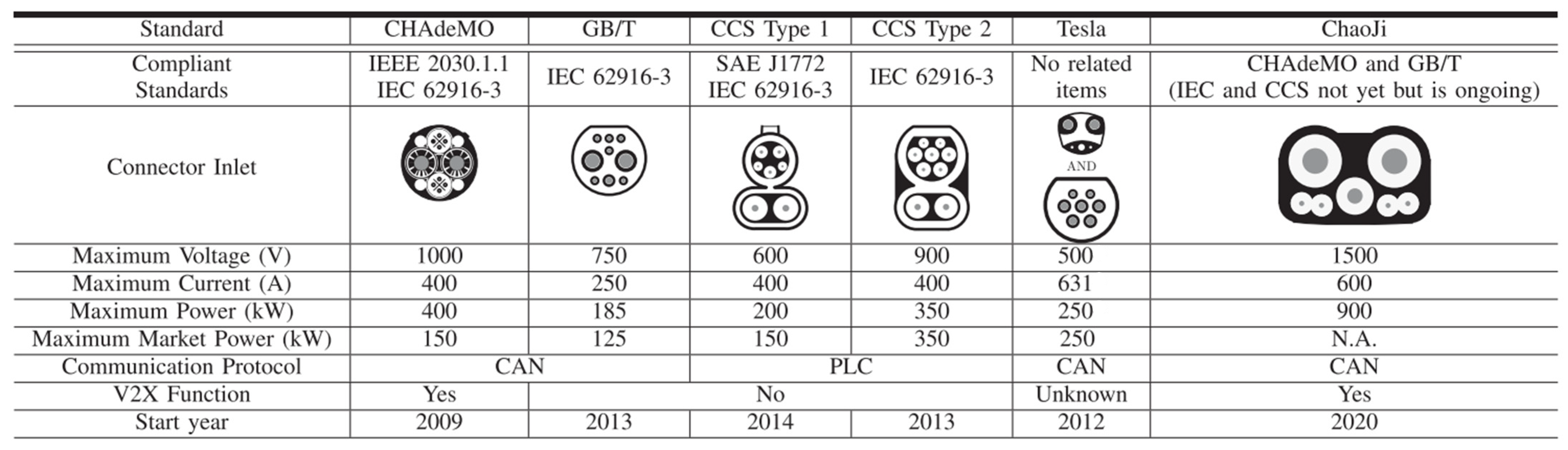
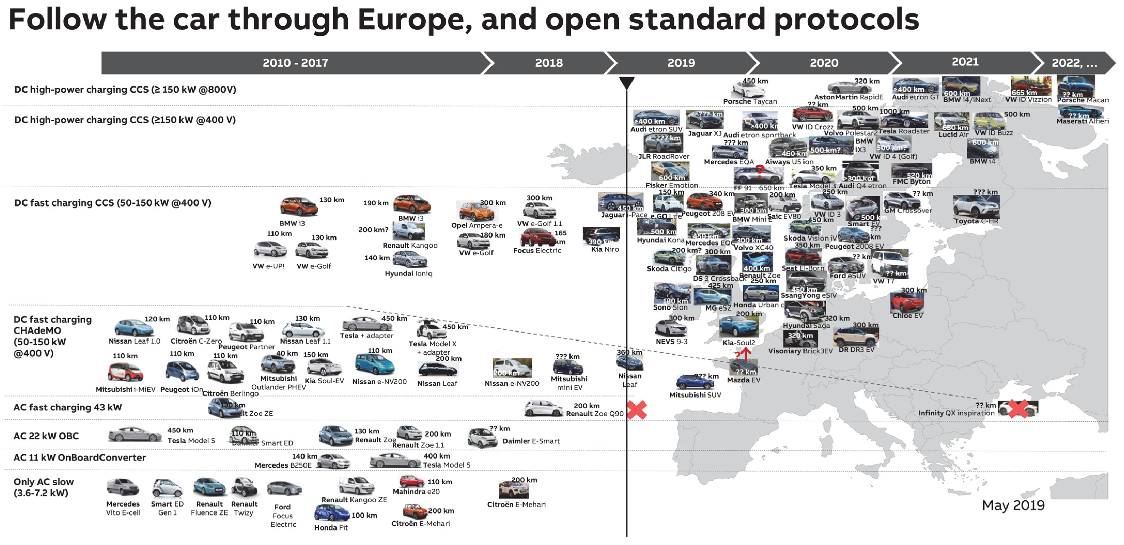
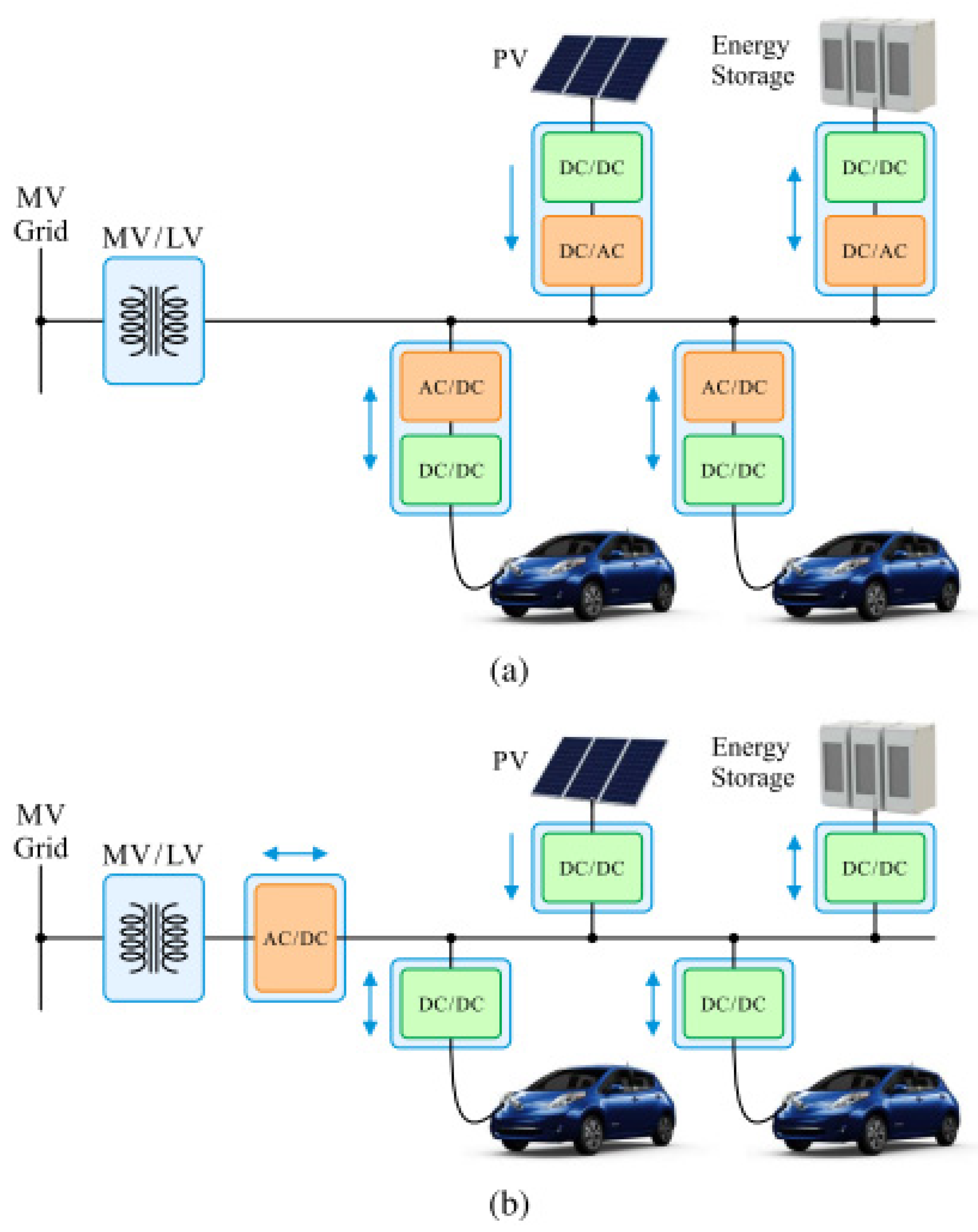
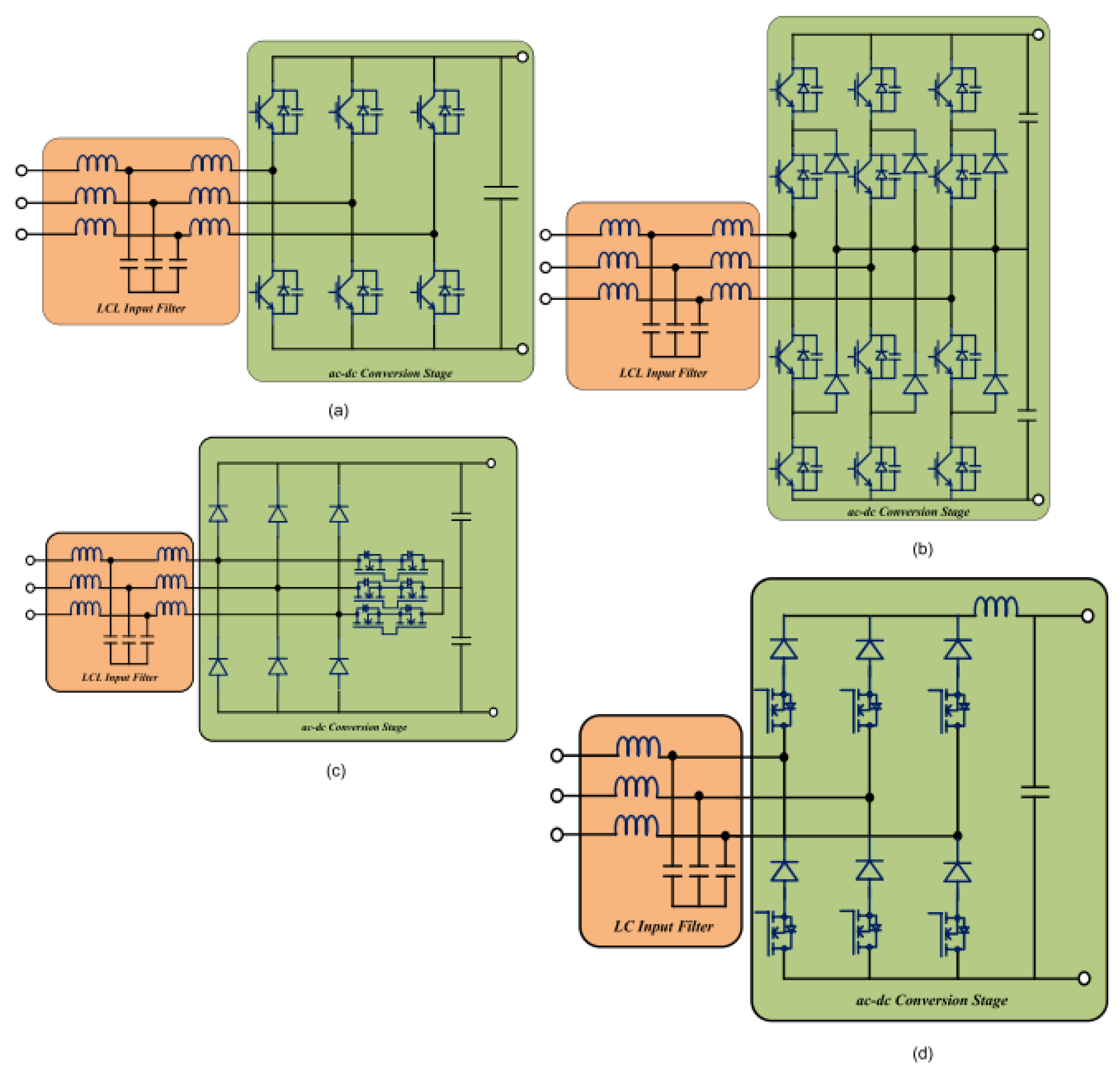
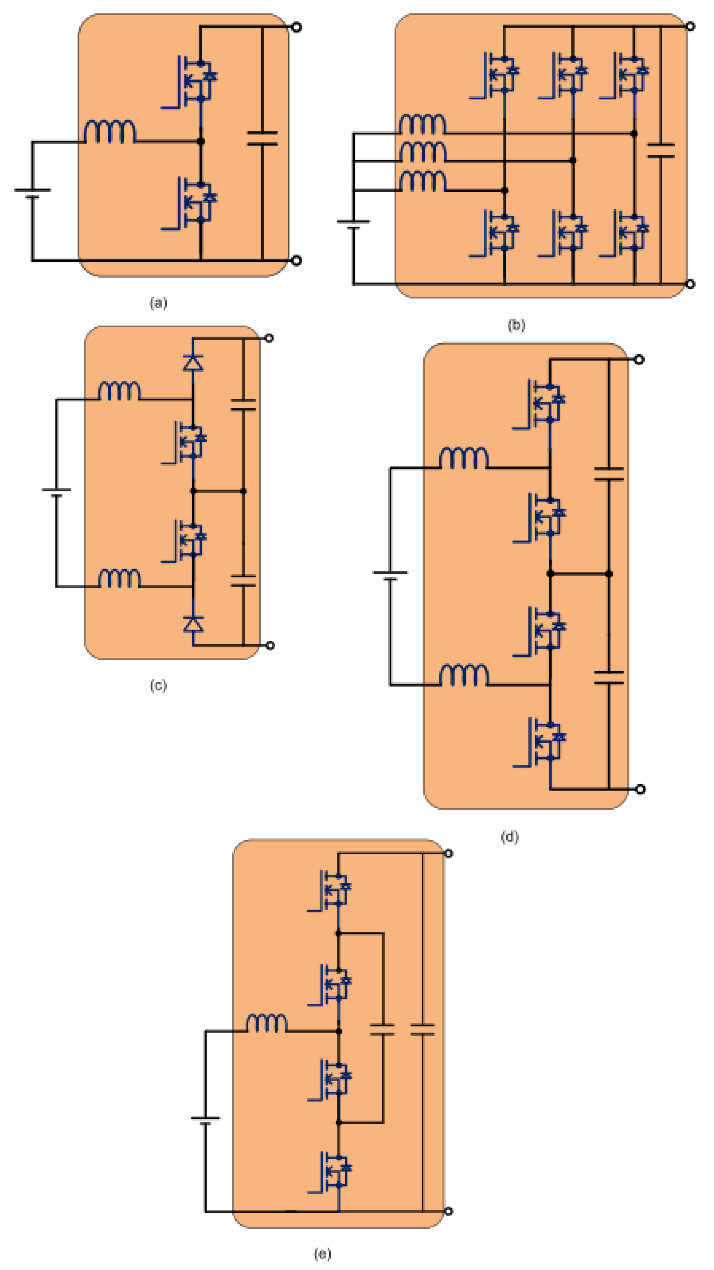
Table 1.
Technical specifications of the state-of-the-art DCFCs (Reprinted with permission from Ref. [6]. Copyright 2019 IEEE).
Table 1.
Technical specifications of the state-of-the-art DCFCs (Reprinted with permission from Ref. [6]. Copyright 2019 IEEE).
| Model | Power (kW) | Input Voltage (Vac) | Output Voltage (Vdc) | Output Current (A) | Efficiency | Volume (L) | Weight (kg) | Time for 200 Miles Drive (Min) |
|---|---|---|---|---|---|---|---|---|
| ABB Terra 53 (CCS Type 1 CHAdeMo 1) | 50 | 480 | 200–500 50–500 | 120 | 94% | 78 | 400 | 72 |
| Tritium Veefil-RT (CCS Type 1&2 CHAdeMo 1) | 50 | 380–480 | 200–500 50–500 | 125 | >92% | 495 | 165 | 72 |
| Phihong Integrated (GB/T) | 120 | 380 (±15%) 480 (±15%) | 200–750 | 240 | 93.5% | 591 | 240 | 30 |
| Tesla Supercharger | 135 | 380–480 | 50–410 | 330 | 91% | 1047 | 600 | 27 |
| EVTEC espresso&charge (SAE Combo-1 CHAdeMo 1) | 150 | 400 (±10%) | 170–500 | 300 | 93% | 1581 | 400 | 24 |
| ABB Terra HP (SAE Combo-1 CHAdeMo 1.2) | 350 | 400 (±10%) | 150–92 | 375 | 95% | 1894 | 1340 | 10 |
Table 2.
Comparison of various isolated and non-isolated DC/DC converter topologies for DCFCs (Reprinted with permission from Ref. [6]. Copyright 2019 IEEE).
Table 2.
Comparison of various isolated and non-isolated DC/DC converter topologies for DCFCs (Reprinted with permission from Ref. [6]. Copyright 2019 IEEE).
| Converter | Type | Switches/Diodes | Bidirectional | Advantages/Disadvantages |
|---|---|---|---|---|
| PFSB converter | Isolated | 4/4 | No |
|
| LLC converter | Isolated | 4/4 | No |
|
| DAB converter | Isolated | 8/0 | Yes |
|
| CLLC converter | Isolated | 8/0 | Yes |
|
| Boost Converter | Non-isolated | 2/0 | Yes |
|
| Interleaved boost converter | Non-isolated | 6/0 | Yes |
|
| Three-level boost converter | Non-isolated | 4/0 | Yes |
|
| Flying capacitor converter | Non-isolated | 4/0 | Yes |
|
Table 3.
DC fast charging grid impacts and management.
| DCFC Grid Impact | Factors | Planning or Management Approach | References |
|---|---|---|---|
| Peak demand | SoC, start time, travel distance, environment, i.e., weather, and ambient temperature, electricity price. | Monte Carlo simulations, controlled charging, TOU, demand side management. | [11,67,130,131,132,133,134,135,136] |
| Harmonic distortions | Harmonic emissions, Supraharmonics, Harmonic stability. | S-VSC and AFE, battery storage, flywheel, SMES, controlled charging. | [11,112,113,137,138] |
| Transformer overloading | Cable, line loading, infrastructure, losses. | Controlled charging, Monte Carlo simulations. | [139,140,141,142,143] |
| Voltage fluctuations | Light flicker, SoC, EV arrival time. | Controlled charging, Monte Carlo simulations. | [11,131,132] |
Publisher’s Note: MDPI stays neutral with regard to jurisdictional claims in published maps and institutional affiliations. |
© 2022 by the authors. Licensee MDPI, Basel, Switzerland. This article is an open access article distributed under the terms and conditions of the Creative Commons Attribution (CC BY) license (https://creativecommons.org/licenses/by/4.0/).
Share and Cite
MDPI and ACS Style
Town, G.; Taghizadeh, S.; Deilami, S. Review of Fast Charging for Electrified Transport: Demand, Technology, Systems, and Planning. Energies 2022, 15, 1276. https://doi.org/10.3390/en15041276
AMA Style
Town G, Taghizadeh S, Deilami S. Review of Fast Charging for Electrified Transport: Demand, Technology, Systems, and Planning. Energies. 2022; 15(4):1276. https://doi.org/10.3390/en15041276
Chicago/Turabian StyleTown, Graham, Seyedfoad Taghizadeh, and Sara Deilami. 2022. "Review of Fast Charging for Electrified Transport: Demand, Technology, Systems, and Planning" Energies 15, no. 4: 1276. https://doi.org/10.3390/en15041276
Note that from the first issue of 2016, this journal uses article numbers instead of page numbers. See further details here.