
Value-Added Pyrolysis of Waste Sourced High Molecular Weight Hydrocarbon Mixtures


Research Centre for Biochemical, Environmental and Chemical Engineering, Department of MOL Hydrocarbon & Coal Processing, Faculty of Engineering, University of Pannonia, H-8200 Veszprém, Hungary
*
Author to whom correspondence should be addressed.
Energies 2022, 15(3), 997; https://doi.org/10.3390/en15030997
Submission received: 27 December 2021
/
Revised: 21 January 2022
/
Accepted: 26 January 2022
/
Published: 28 January 2022
Abstract
:In this study, Fischer-Tropsch paraffin mixture, heavy residue of waste polyethylene pyrolysis, shredded and crashed agricultural polyethylene waste and their combinations were pyrolysed both thermally and catalytically in a two-stage reactor system. During the experimental work, yields and compositions of pyrolysis products were studied as function of feedstock composition and catalyst placement. It was found that the average molecular weight of feedstocks and the presence of ZSM-5 catalyst also have significant effects on the product yields and the compositions. Feedstocks with high concentration of Fischer-Tropsch paraffin and real waste polyethylene resulted in deeper fragmentation in both thermal and thermo-catalytic pyrolysis. Due to the deeper fragmentation, they seemed to be suitable feedstocks for the production of C6–C9 and C10–C14 hydrocarbons. Meanwhile, for production of C15–C21 hydrocarbons, the use of a higher concentration of heavy residue of waste polyethylene pyrolysis in the feedstocks is recommended. From the point of view of liquid hydrocarbon and isomer production, the placement of the catalyst into the 1st reactor proved to be more advantageous. When the catalyst was placed into the 2nd reactor, the product formation shifted to the more volatiles, isomers took part in secondary cracking reactions and aromatics formed in higher concentrations.
1. Introduction
Nowadays, the biggest challenge to humanity has been the fight against the climate change. In order to achieve these goals, one of the most effective ways is to reduce greenhouse gas (GHGs) emissions. The energy related carbon has been accounting for approximately 65% of the emission of GHGs, which means 33.9 × 10⁹ metric tons of carbon-dioxide (2018) [1]. To mitigate the effects of climate change, the EU and countries around the world have defined various climate goals, packages, regulations, and directives. One such package was the Climate and Energy Package [2]—which included the Renewable Energy Directive (RED) [3]—in order to achieve the climate goals set for 2020, or the recently announced ’FIT for 55’ package [4] which aims to cut the emissions by at least 55% by 2030. Biomass-related technologies have played a serious role in these measurements [2,3,4].
Hydrocarbon production from syngas—CO and H2—derived from coal gasification was discovered in 1923 by German scientists Franz Fischer and Hans Tropsch [5]. The process is called Fischer-Tropsch (FT) synthesis. Coal gasification is not the only way to produce syngas, but also natural gas [6], and biomass-based feedstocks [7,8] can be used. Carbon Capture and Utilisation technologies, and water electrolysis also seem to be suitable to obtain FT syngas [9]. The importance of Fischer-Tropsch synthesis is growing year by year, but some challenges still remain [10].
In low-temperature Fischer-Tropsch synthesis (LTFT, T < 250 °C), a hydrocarbon fraction, which contains more than 95% C22-C60 paraffins with a significantly high yield (approx. 40–45%) is formed. This fraction has a boiling point of higher than 360 °C, known as FT wax [11]. FT waxes are low-value products, therefore value-adding conversions seem to be necessary. The most commonly used technologies are hydroconversion processes (hydrotreating, hydrocracking, hydroisomerisation) [12,13,14,15]. Due to the applied hydrogen atmosphere, the products obtained from FT wax hydrocracking mainly contain saturated hydrocarbons (n- and isoparaffins) [12]. Because of the composition, the petroleum and diesel fraction obtained by FT wax hydrocracking can be used as an excellent fuel blending component (good cold flow properties with relatively high cetane number). Due to the extended amount of n-paraffins and the lack of olefin and aromatic hydrocarbons, the obtained gasoline fraction has a low octane number. Light products of the hydrocracking include mostly propane and butane, which can be utilized as LPG [12,13,14,15].
Value-added petrochemical feedstocks from FT waxes (e.g., C3–C4 and α-olefins) can be produced by thermal and thermo-catalytic cracking [16,17,18,19,20]. In case of thermal cracking, the yield of heavy products (which has boiling point higher than 360 °C) can be 50–60%, therefore catalytic cracking seems to be more advantageous in terms of product distribution [16]. It is possible to produce light olefins and gasoline fractions with a high research octane number using Fluid Catalytic Cracking of FT waxes (naphtha yield can be even 70%) [21]. In addition, hydroconversion processes require a significant amount of high quality hydrogen, which usually acts as a bottleneck in conventional refineries [22]. Due to the reasons mentioned above, it may be worthwhile to examine and increase the efficiency of other conversion processes aside from hydroconversion.
Another primary challenge is to handle the plastic waste produced globally. Plastic production and demand is increasing year by year. In the year of 2019, plastic production has been reached 368 million metric tons worldwide [23]. Packaging plastics, such as polyolefins (HDPE, LDPE, PP), PET, and PS, etc. hold a significant share in demand for plastics in the EU, of approx. 40%, which was 50.7 million metric tons in 2019 [23]. Mass of Mismanaged Plastic Waste like urban litter, and open dumps, etc.—according to current trends—may reach 155–265 metric tons by 2060 [24].
Chemical recycling as a part of the circular economy plays an important role in current and future plastic strategies in the EU. During chemical recycling, products which are usually obtained by conventional crude oil refining and/or petrochemical processes, can be formed; therefore it can assist in reducing emissions, and the dependence on fossil fuels [25]. In many cases, it can be more advantageous than other methods such as mechanical recycling, where deterioration of performance properties of products can easily occur [26].
Common methods for polyolefin chemical recycling are thermal and thermo-catalytic pyrolysis processes, when the waste plastics decomposes to shorter chain hydrocarbon fractions such as gases, liquid products and longer carbon-chain wax, due to the applied temperature (usually above 300 °C) and/or catalyst [27]. Catalyst application is usually more effective, because it reduces the activation energy of the reaction (therefore the applicable temperature) and fastens its rate, which causes smaller residence time and extended the liquid-product yield. Acidic catalysts such as zeolites (HZSM-5, HUSY), Al2O3-SiO2, FCC and reforming catalysts, as well as mesoporous materials (e.g., MCM-41) have been most commonly used [28].
Long-chain hydrocarbon formation occurs in both thermal and thermo-catalytic plastic pyrolysis. This fraction, which contains mostly C21+ paraffins and olefins, can be referred to as pyro-waxes [29,30]. These waxes can also be converted with hydro-, thermal-, and thermo-catalytic pyrolysis to produce value-added hydrocarbons, e.g., fuels, olefin containing gases, α-olefins, and aromatics depending on the applied conversion process [31,32,33,34].
Due to the similar compositional characteristics, co-processing of FT waxes, waste polyolefins, and polyolefin pyro-waxes, is possible in the same catalytic system, with both thermal and thermo-catalytic processes. Co-pyrolysis of various high molecular weight alternative hydrocarbons (and polymers) has been a widely researched field recently. Significant developments can be observed in the field of biomass co-pyrolysis with polyolefins [35,36,37,38,39,40]; however there is a research gap in terms of pyro-waxes [41] and Fischer-Tropsch wax or other conventional high molecular weight paraffin wax co-processing [42]. Limited publications are available about the influence of catalyst layout and the way of contact (direct contact with the feed or contact with vapours from previous thermal cracking step), for the product yield and composition.
2. Materials and Methods
Based on the abovementioned factors, the aim of the experimental work was to study the value-added pyrolysis of high molecular weight hydrocarbon mixtures as the function of the feedstock composition and the catalyst layout.
2.1. Feedstock
Fischer-Tropsch paraffin mixture (FT wax) from South Africa (Sasol), heavy residue obtained previously from waste polyethylene pyrolysis (WPEHR), shredded and crashed polyethylene waste (WPE) from Hungarian agricultural sector and their mixtures were used as feedstock.
Commercial FT wax was composed of molecules with a C13-C69 carbon number range, mainly C21+ aliphatic hydrocarbons (99.2%) and was virtually free of sulphur and aromatics. The WPEHR was obtained via the thermal pyrolysis of waste polyethylene. Details about the production process can be found elsewhere [43]. Similar to the Fischer-Tropsch paraffin mixture, WPEHR also contained mainly aliphatic hydrocarbons (19.0% of n-paraffins and 63.8% of n-olefins) from the carbon number range of C9–C48 (C21+ hydrocarbon content: 63.3%). It is important to note that WPEHR is a low-value by-product with an initial boiling point of above 360 °C. Nonetheless, this fraction could even act as a feedstock for the production of heavy engine fuels due to the high aliphatic hydrocarbon content. However, the feasibility of this process has not been widely explored in the literature, especially in combination with other high molecular weight hydrocarbon mixtures such as WPE. To identify the kinds of polymers, a representative amount of WPE was analysed by a Fourier-transformed infrared spectroscopic method and each particle was weighted using the laboratory scale. Based on the results, the WPE contained 99.5% HDPE.
To increase the efficiency of the pyrolysis reaction, a commercial ZSM-5 catalyst was used (Zeolyst International, Si/Al molar ratio: 23, BET surface area: 425 m2/g). The optimal Si/Al ratio was determined in pre-experiments.
2.2. Pyrolysis Process
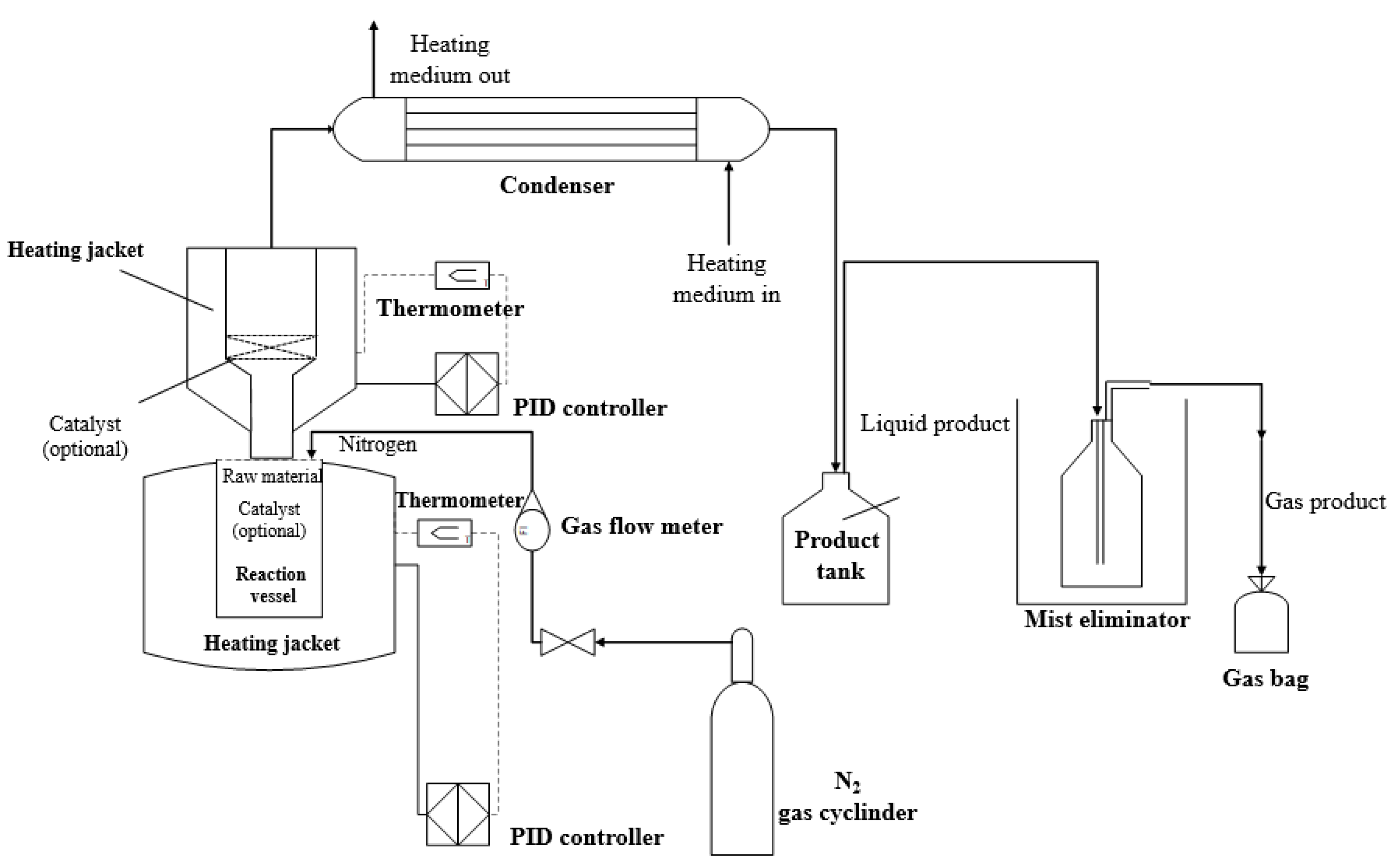
The pyrolysis was carried out in a two-stage reactor system containing two reactors with independent temperature control (Figure 1). Before the experiments, 50 g of feedstock and 1.0 g of ZSM-5 catalyst was mixed mechanically and placed into the 1st reactor. The experiments were also repeated by placing the same catalyst into only the upper (2nd) reactor. In the first case, the feedstock and the catalyst directly contacted each other; meanwhile, in the latter case, the catalyst only came into contact with the product vapours of the first reactor. In order to perform an appropriate comparison, an experiment without catalyst was also performed (thermal pyrolysis) with the same system layout. During the pyrolysis process, nitrogen atmosphere (75 mL/min) was used to avoid oxidation and unfavoured secondary reactions. The temperatures of each reactor (Tmax = 450 °C) was increased using a heating rate of 5 °C/min. The maximum temperature of the pyrolysis was chosen based on the expected product yields. In order to decrease the amount of unconverted feedstock—even without a catalyst—the application of a high temperature (>400 °C) is necessary; however, temperature increasing to around 500 °C results in higher gaseous product yield. Liquid hydrocarbons, as the main product of the process forms around 450–460 °C with the highest yield from thermal cracking of polyolefin feedstock concluded by previous studies [44,45]. Application of this temperature range provides appropriate conversion of FT waxes as well in case of thermal cracking [16].
To control the temperatures PID controllers, a computer and data recorder unit were used. The pyrolysis vapours were condensed into a heat exchanger at 90 °C (chosen with safety considerations 10 °C above the drop melting point of the used FT wax). The non-condensable gases were collected in a gas bag. The amount of liquid products and the residue was determined by weight measurement and the weight of the gaseous products was calculated by the difference.
2.3. Analysis
To characterize the feedstocks, the gas and the liquid pyrolysis products gas chromatography, Fourier-transformed infrared (FTIR) spectroscopy and high-pressure liquid chromatography (HPLC) were used.
The feedstocks and the liquid pyrolysis products were analysed using a DANI type gas chromatograph (GC) fitted with a flame ionization detector (FID). For the analysis, the RTx-1 column (30 m × 0.53 mm × 0.25 μm) was used. Both the injector and the detector temperature were 340 °C, and the heating program was as follows: 40 °C for 5 min and heating to 340 °C (8 °C/min) and held at 340 °C for 28 min. To determine the retention times, commercially available paraffin and olefin standards and paraffin mixtures were used.
The composition of the gas products was also identified by a DANT type GC, comprising FID and thermal conductivity detectors (TCD). The used columns were Rtx-1 PONA (100 m × 0.25 mm × 0.5 μm) and Carboxen TM 1006 PLOT (30 m × 0.53 mm). Samples were analysed on Rtx-1 PONA column under isothermal condition (T = 35 °C) using 230 °C for the injector and detector temperature. In the case of the Carboxen TM 1006 PLOT column, the following temperature program was applied: 35 °C for 18 min, heating to 120 °C (15 °C/min) and held at 120 °C for 2 min. The retention times of the components were determined using gas mixtures of the known composition and individual components.
For the identification of the chemical bonds, FTIR measurements (TENSOR 27 type FTIR-ATR spectrometer) were carried out in the wavenumber range of 4000–400 cm−1. The measurements were made using germanium crystal at room temperature, using 32 scans and a resolution of 3 cm−1.
The aromatic contents were determined using a Shimadzu LC-20AD type HPLC instrument and Shimadzu RID-10A type refractory index detector, using n-heptane diluents.
3. Results and Discussion
3.1. Product Yields
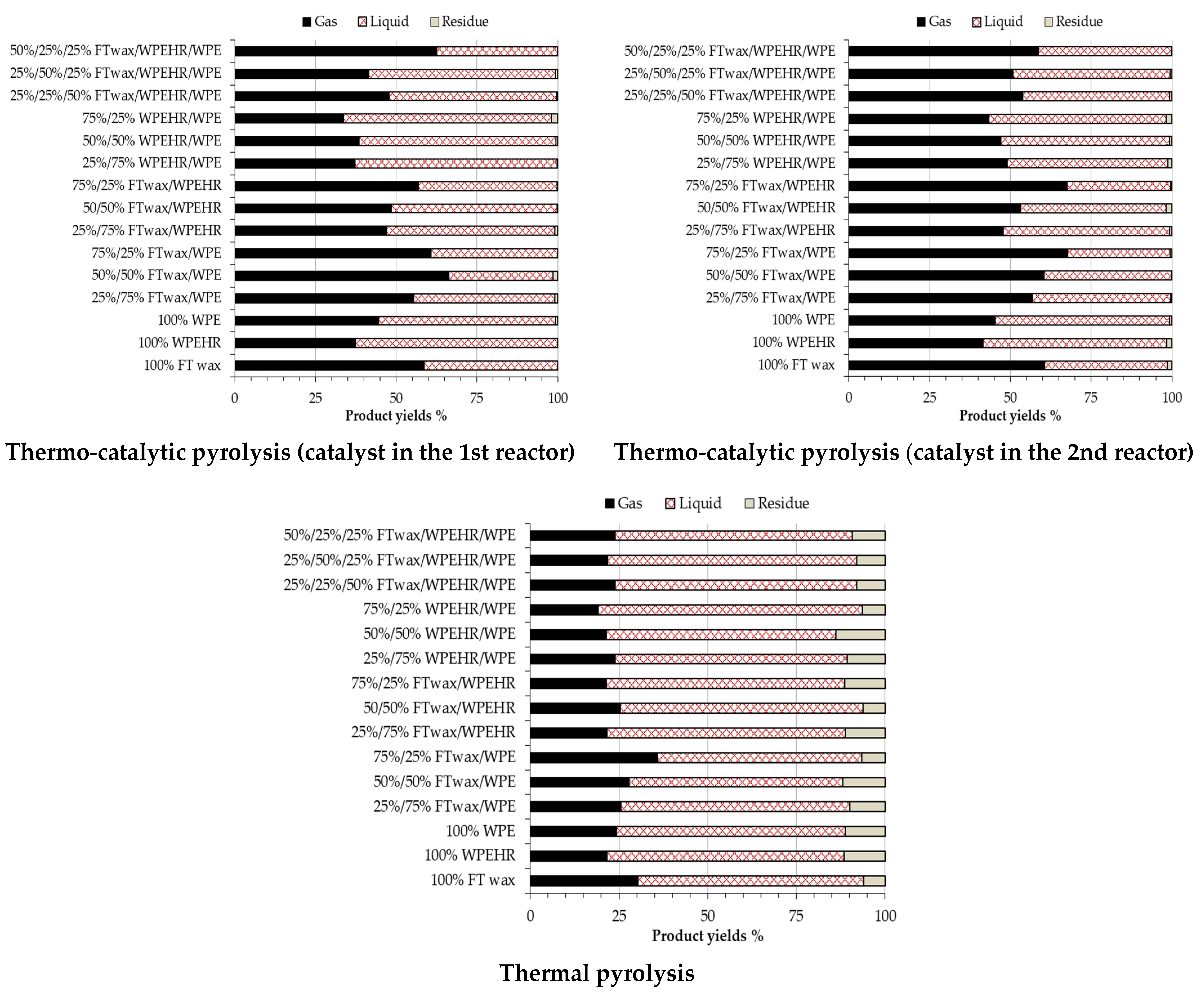
In the thermo-catalytic experiments 33.6–67.8% gas and 31.6–64.4% liquid were formed; meanwhile, the gas and liquid product yields of thermal pyrolysis were 19.2–35.8 and 57.6–74.4%, respectively (Figure 2). As a result of the catalyst, the activation energy of pyrolysis decreased significantly, therefore more intensive C-C bond scission took place and resulted in 1.5–2.0 times higher gas yields. It is important to note that the zeolite framework also had an effect on the gas yields. The 10-membered ring narrow channels of ZSM-5 resulted in a long diffusion path for the intermediate products, therefore the molecules participated in secondary cracking reactions further increasing the gas yields [46]. The gas formation was also enhanced by the pyrolysis of FT wax and WPE containing feedstocks; meanwhile the effect of WPEHR feedstock component was generally opposite on the gaseous state hydrocarbon formation. As it was already mentioned before, WPEHR contained mainly C9-C48 hydrocarbons. In general, shorter-chain hydrocarbons have a higher stability in pyrolysis and their adsorption is also weaker on the catalytically active sites that also contributed to the lower gas-product yields [47].
In addition to the number of carbon atoms in the reactant, the placement of the MFI type catalyst had an effect on the amount of gas and liquid products. Higher gas yields were generally observed when the catalyst was placed into the 2nd reactor. In this case, Brønsted acid sites present in the pores of the ZSM-5 catalyst were totally accessible for the thermally pyrolysed molecules; therefore, a deeper fragmentation took place and the product formation shifted towards the more volatile products. In contrast, when the catalyst was in the 1st reactor, only the active sites of the external surface of the zeolite crystallites participated in the catalysis. Artexte et al. [48] made a similar finding in their two-step thermal and catalytic experiments.
3.2. Gaseous Products
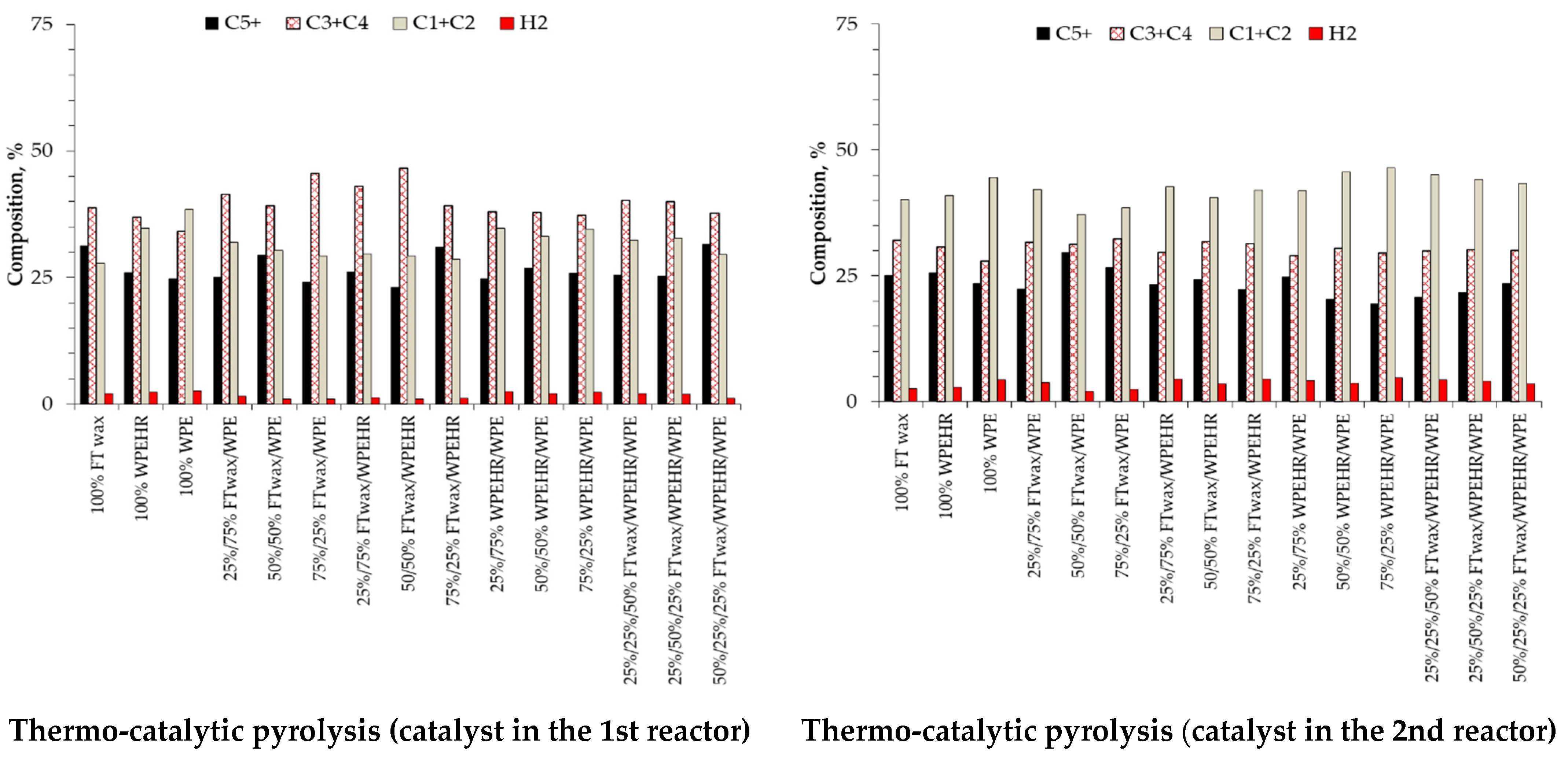
The composition of gaseous products is shown in Figure 3. The gas products consisted of hydrogen and C1–C6 hydrocarbons. As can be seen from the data, the feedstock composition had a slight effect on the gas compositions, but the presence of the catalyst had a more significant affect. Without the catalyst, the gas products contained mainly C3–C4 hydrocarbons (49.1–62.2%). The amount of C1–C2 hydrocarbons was around 25%, and the hydrogen contents changed between 1.3 and 3.0%. In terms of thermo-catalytic pyrolysis—particularly when the catalyst was placed into the 2nd reactor—37.2–46.5% C1–C2 hydrocarbon was formed and the hydrogen contents was around 1.5–2.0 times higher. The increased amount of hydrogen can be attributed to propane and butane dehydrogenation [49]. The increased C1–C2 formation can be attributed to the fully accessible Brønsted acid sites in the micropores, the long diffusion path and the deeper fragmentation, but it can also be associated with aromatic hydrocarbon formation.
The formation of aromatics form C3-C4 hydrocarbons over ZSM-5 catalyst is a well-known reaction mechanism. Unlike methane, C3-C4 hydrocarbons undergo secondary transformation reactions like dehydrogenation and oligomerisation. In case of ethane, the initializing dehydrogenation step is approximately 30 times slower than propane, and 100 times in the case of butane; therefore, ethane is an undesired product in terms of aromatic-hydrocarbon formation. In oligomerisation reactions, higher hydrocarbons can be formed. These secondary higher hydrocarbons can undergo cyclisation (or cracking) which obtains aromatic hydrocarbons [49].
3.3. Liquid Products
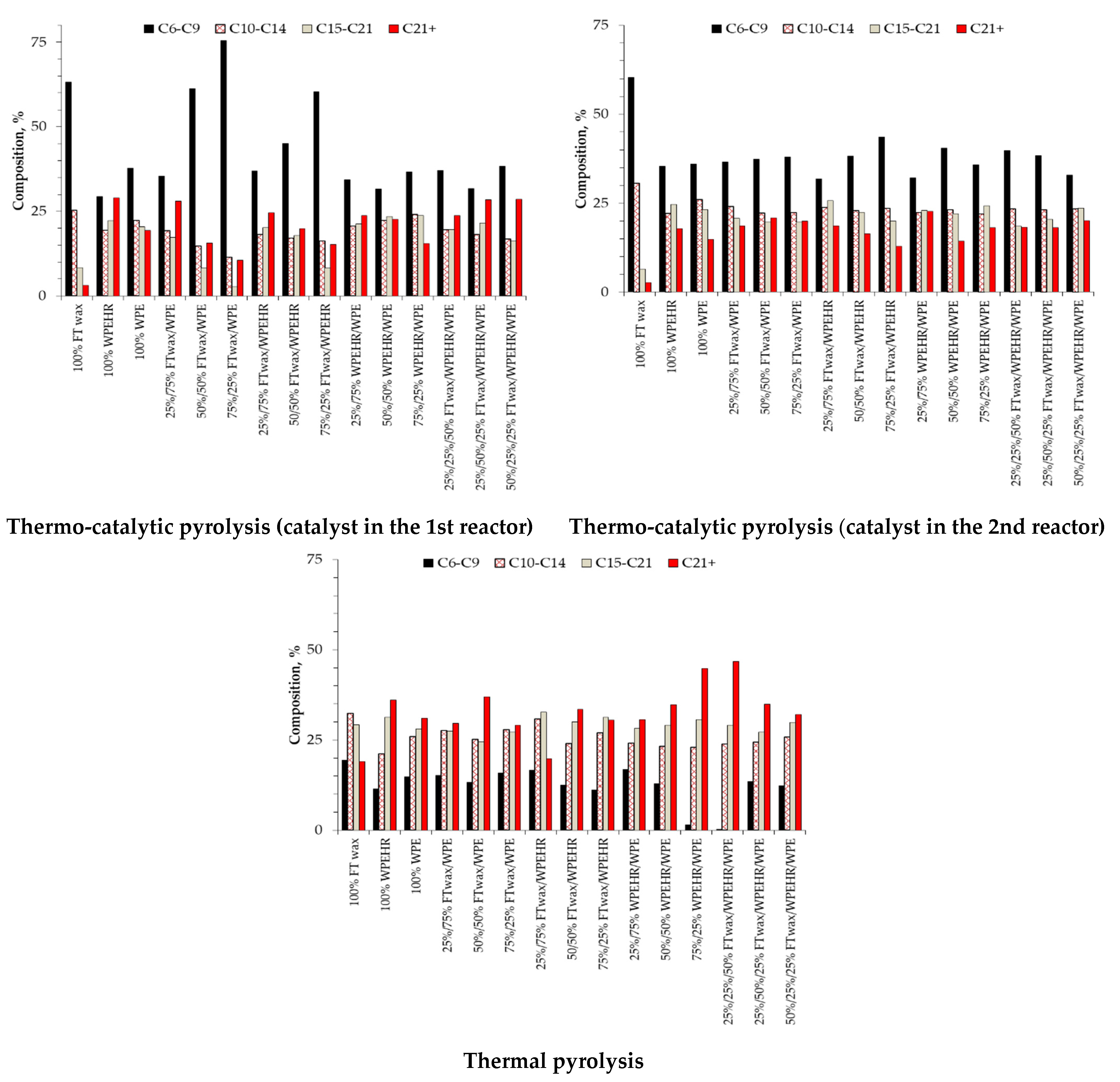
During the thermal and thermo-catalytic pyrolysis experiments, 31.6–74.4% of liquid products (C6–C45) were formed and analysed by GC. As Figure 4 represents, the liquid pyrolysis products contained mainly C6–C9 hydrocarbons with 18.2–32.4% of C10–C14 and 2.6–44.7% of C15–C21 hydrocarbon content.
The highest C6–C9 and C10–C14 hydrocarbon concentrations were generally identified in the pyrolysis products of the higher FT wax and WPE containing feedstocks (e.g., 100% FT wax, 75%/25% FT wax/WPE, 50%/50% FT wax/WPE). In contrast, for the production of C15–C21 hydrocarbons, the higher WPEHR containing feedstocks—such as 100% WPEHR, 25%/75% FT wax/WPEHR, 75%/25% WPEHR/WPE—seemed to be more suitable. As the data show, the pyrolysis of higher molecular weight feedstocks (e.g., FT wax, FT wax and WPE mixtures) resulted in deeper fragmentation, while in the presence of the heavy residue of waste polyethylene (WPEHR) the counterbalance of this effect occurred. Heavier hydrocarbons have lower stability in pyrolysis process, their degradation begins at much lower temperatures and thus also results in a higher extent of conversion [47]. In the thermal pyrolysis experiments, about 53.2–81.0% of C6–C21 hydrocarbons were produced. When the strongly acidic and narrower-pore sized ZSM-5 catalyst was used, the C6–C21 hydrocarbon contents increased by 1.2–29.3%. From the point of view of C6–C21 hydrocarbon production placing the catalyst into the 2nd reactor proved to be more advantageous because of the higher conversion.
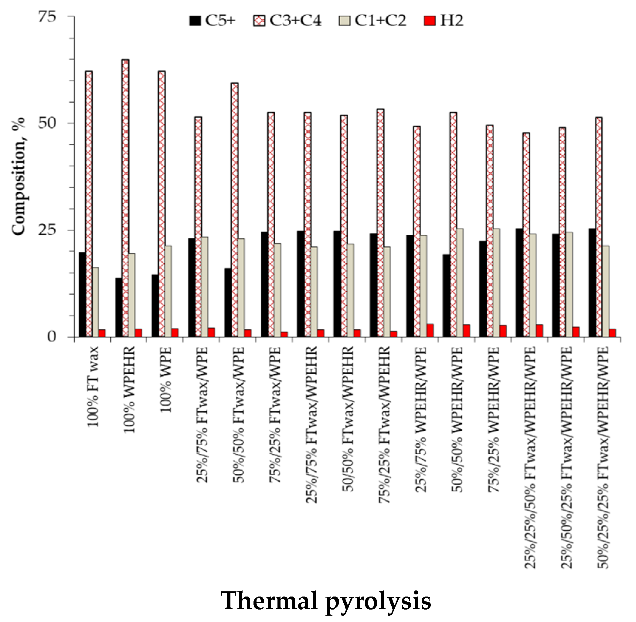
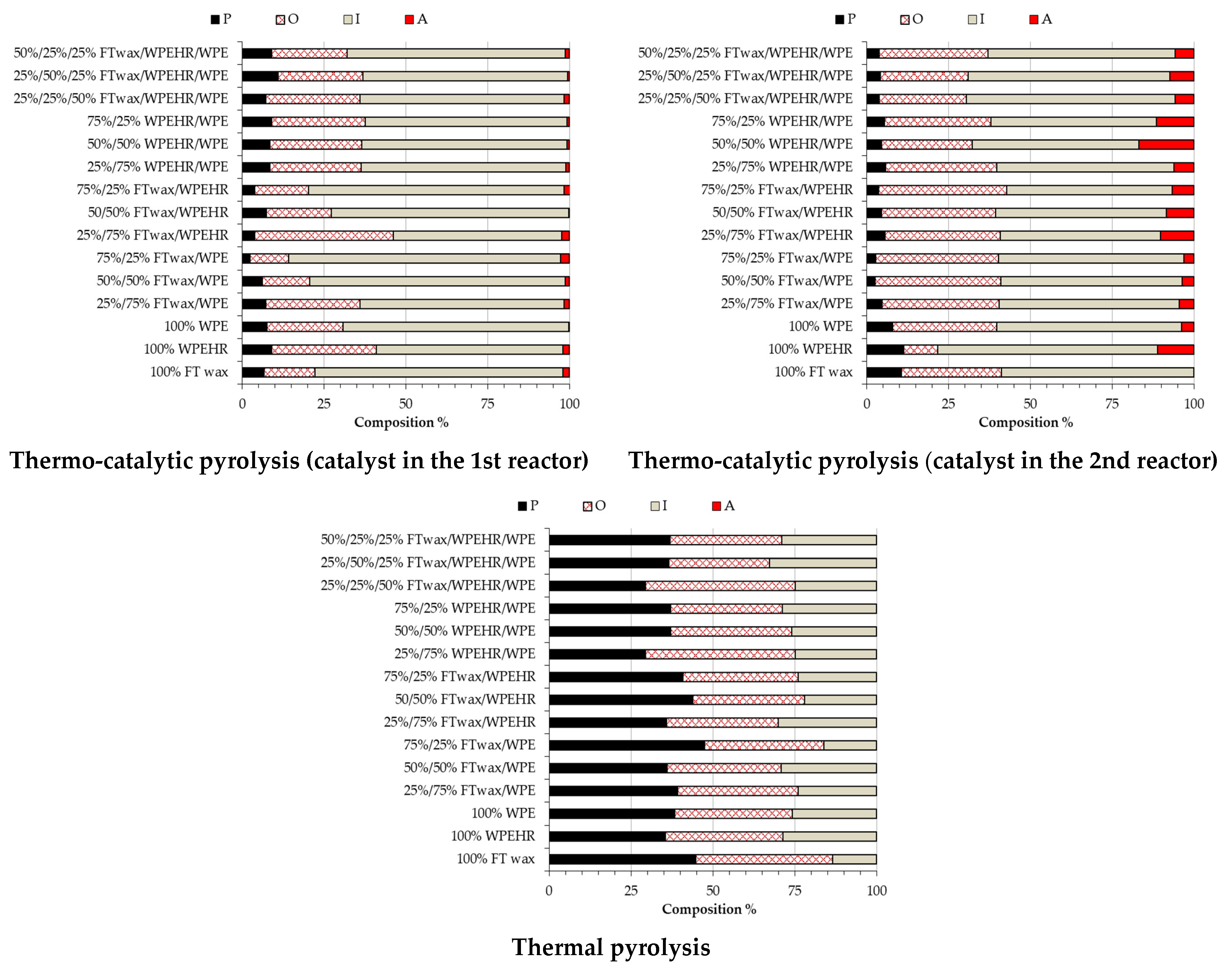
The hydrocarbon composition of liquid pyrolysis products can be grouped into the following four categories; paraffins, olefins, isomers and aromatics. As data of Figure 5 shows, liquid products of thermal pyrolysis were free from aromatics. During the thermal conversion aliphatic hydrocarbons were mainly formed, and the degree of isomerization was only minor. The lower isomer contents can be attributed to the radical reaction mechanism of the thermal pyrolysis. In this case, no rearrangement occurred; branched hydrocarbons can only be produced by recombination of the radicals. In contrast, thermo-catalytic pyrolysis follows a carbocationic mechanism and rearrangement also takes place [50].
In thermo-catalytic pyrolysis, the conversion of higher molecular weight feedstocks resulted in a higher isomer contents. The most significant isomer formation was observed in the pyrolysis of 75%/25% FT wax/WPE, 50%/50% FT wax/WPE and 100% FT wax feedstocks. When using the catalyst, the isomer contents increased by 19–69%. Beside this, catalyst placement also had a significant effect on the isomer contents. Placing the catalyst into the 1st reactor, the isomer contents varied between 51.5 and 83.0%; meanwhile, the 2nd reactor resulted in an isomer contents of 49.0–67.2%. Isomerization and aromatization reactions are competing and take place at the same catalytically active sites. In addition, branched carbocations are unstable, reactive compounds, which spend a relatively long time in the zigzag channels of the ZSM-5 catalyst. It is a generally accepted fact that pore size of ZSM-5 does not favour the formation of multiple branched hydrocarbons having larger critical molecular size [51]. Moreover, cracking of the single-branched carbocations resulted in the formation of two linear hydrocarbons which can contribute to the lower isomer contents.
ZSM-5 zeolite also favoured the formation of aromatic hydrocarbons. As a result, 0.2–2.8 and 2.3–16.9% of aromatic hydrocarbons were formed in thermo-catalytic pyrolysis. Higher values were observed in those experiments when the catalyst was filled into the 2nd reactor and WPEHR containing feedstocks were converted into more valuable hydrocarbons. As the data of Figure 5 shows, the aromatic contents were generally increased with the WPEHR content, while the effect of FT wax on aromatics was the opposite. The high aromatization activity of zeolite ZSM-5 is a widely known fact, and can be attributed to its narrower 10-membered ring channels and their zigzag pattern [49,52]. In the experiments, polyaromatics were not formed, because the shape selectivity in the microporous structures of ZSM-5 hindered their formation [53].
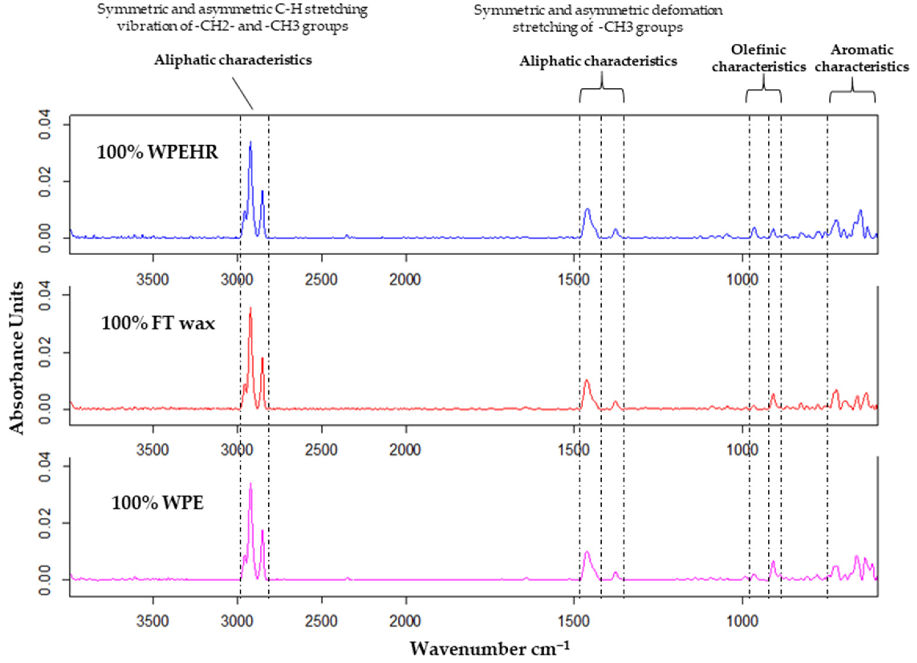
The formation of paraffin, olefin and aromatic hydrocarbons was demonstrated by the results of FTIR spectroscopy (Figure 6). Since all of the spectra were very similar, only the results of thermo-catalytic pyrolysis of 100% WPEHR, 100% FT wax and 100% WPE are shown graphically. In spectra, the typical vibration bands of symmetric and asymmetric methyl and methylene hydrocarbon groups appeared in the range of 3000–2800 cm−1. The appearance of methyl and methylene groups were referred to as the aliphatic characteristics of the pyrolysis products. The peaks at 1380 and 1460 cm−1 belong to C-H bonds and also indicated the presence of aliphatic groups. The olefinic characteristics were justified by the appearance of bands at 1640 cm−1 and in the range of 1000–850 cm−1. The peaks appeared at 910 and 980 cm−1 and referred to the vibration of vinyl-type olefins; meanwhile, the appearance of a peak at 890 cm−1 justified the formation of vinylidene olefins. As the spectra represent, the bands which are mainly characteristics in monosubstituted aromatic compounds was appeared at 670 and 720 cm−1.
4. Conclusions
In this study, Fischer-Tropsch paraffin mixture (FT wax), heavy residue of waste polyethylene pyrolysis (WPEHR), shredded and crashed agricultural polyethylene waste (WPE) and their combinations were pyrolysed both thermally and catalytically in a two-stage reactor system. During the experimental work. The yields and compositions of the pyrolysis products were studied as the function of feedstock composition and catalyst placement. Based on the results, it was found that the average molecular weight of feedstocks and the placement of the ZSM-5 catalyst also have significant effects on the product yields and the compositions. Both in thermal and thermo-catalytic pyrolysis, higher FT wax and WPE containing feedstocks showed the highest activity and resulted in deeper fragmentation. Due to the deeper fragmentation, they seemed to be favourable feedstocks for the production of C6–C9 and C10–C14 hydrocarbons. Meanwhile, for the production of C15–C21 hydrocarbons, the use of higher WPEHR-containing feedstocks is recommended. From the point of view of the production of liquid state hydrocarbons and isomers, the placement of the catalyst into the 1st reactor proved to be more advantageous. When the catalyst was placed into the 2nd reactor, the product formation is shifted to the more volatiles, and isomers take place in secondary cracking reactions.
Author Contributions
Conceptualization, S.T. and N.M.; Formal analysis, D.H.; Investigation, D.H. and S.T.; Methodology, D.H., S.T. and N.M.; Supervision, S.T. and N.M.; Validation, S.T.; Visualization, D.H.; Writing—original draft, D.H., S.T. and N.M.; Writing—review and editing, D.H., S.T. and N.M. All authors have read and agreed to the published version of the manuscript.
Funding
This publication has been supported by the National Research, Development and Innovation Office through the project nr. 2019-1.3.1-KK-2019-00015, titled “Establishment of a circular economy-based sustainability competence center at the University of Pannonia”.
Institutional Review Board Statement
Not applicable.
Informed Consent Statement
Not applicable.
Data Availability Statement
Not applicable.
Conflicts of Interest
The authors declare no conflict of interest.
Abbreviations
| ATR | Attenuated total reflection |
| FCC | Fluid Catalytic Cracking |
| FID | Flame ionization detector |
| FT wax | Fischer-Tropsch paraffin wax |
| FTIR | Fourier transform infrared spectroscopy |
| GC | Gas chromatography |
| GHG | Greenhouse gas |
| HDPE | High density polyethylene |
| HPLC | High-performance liquid chromatography |
| HUSY | H form of Ultrastable Y Zeolite |
| HZSM-5 | H form of ZSM-5 |
| LDPE | Low density polyethylene |
| LPG | Liquefied Petroleum Gas |
| MCM-41 | Mobil Composition of Matter No. 41 mesoporous silica |
| PET | Polyethylene terephthalate |
| PP | Polypropylene |
| PS | Polystyrene |
| RED | Renewable Energy Directive |
| TCD | Thermal conductivity detector |
| WPE | Polyethylene waste form agriculture sector |
| WPEHR | High molecular weight residue from polyethilene pyrolysis |
| ZSM-5 | Zeolite Socony Mobil–5 catalyst |
References
- BP. Energy Outlook, 2020 ed.; BP: London, UK, 2020; Available online: https://www.bp.com/en/global/corporate/energy-economics/energy-outlook.html (accessed on 10 December 2021).
- European Commission’s 2020 Climate & Energy Package. Available online: https://ec.europa.eu/clima/eu-action/climate-strategies-targets/2020-climate-energy-package_en#tab-0-0 (accessed on 9 December 2021).
- Directive 2009/28/EC of the European Parliament and of the Council of 23 April 2009; European Parliament, Council of the European Union: Brussels, Belgium 2009. Available online: https://eur-lex.europa.eu/legal-content/EN/ALL/?uri=celex%3A32009L0028 (accessed on 10 December 2021).
- Council of the European Union: Fit for 55—The EU’s Plan for Green Transition. Available online: https://www.consilium.europa.eu/hu/policies/green-deal/eu-plan-for-a-green-transition/ (accessed on 9 December 2021).
- Fischer, F.; Tropsch, H. Über die Herstellung synthetischer Ölgemische (Synthol) durch Aufbau aus Kohlenoxyd und Wasserstoff. Brennst. Chem. 1923, 4, 276–285. [Google Scholar]
- Ruiz, J.A.C.; Passos, F.B.; Bueno, J.M.C.; Souza-Aquiar, E.F.; Mattos, L.V.; Noronha, F.B. Syngas production by autothermal reforming of methane on supported platinum catalysts. Appl. Catal. A 2008, 334, 259–267. [Google Scholar] [CrossRef]
- Ail, S.S.; Dasappa, S. Biomass to liquid transportation fuel via Fischer Tropsch synthesis–Technology review and current scenario. Renew. Sustain. Energy Rev. 2016, 58, 267–286. [Google Scholar] [CrossRef]
- Hakawati, R.; Smyth, B.; Daly, H.; McCullough, G.; Rooney, D. Is the Fischer-Tropsch Conversion of Biogas-Derived Syngas to Liquid Fuels Feasible at Atmospheric Pressure? Energies 2019, 12, 1031. [Google Scholar] [CrossRef] [Green Version]
- Hannula, I.; Kaisalo, N.; Simell, P. Preparation of Synthesis Gas from CO2 for Fischer–Tropsch Synthesis—Comparison of Alternative Process Configurations. C-J. Carbon Res. 2020, 6, 55. [Google Scholar] [CrossRef]
- Todic, B.; Nowicki, L.; Nikacevic, N.; Bukur, D.B. Fischer–Tropsch synthesis product selectivity over an industrial iron-based catalyst: Effect of process conditions. Catal. Today 2016, 261, 28–39. [Google Scholar] [CrossRef] [Green Version]
- De Klerk, A.; Furimsky, E. Catalysis in the Refining of Fischer-Tropsch Syncrude. In Catalysis Series; Hargreaves, J.S.J., Rodriguez, J., Bitter, H., Eds.; RSC Publishing: London, UK, 2010. [Google Scholar] [CrossRef]
- Pleyer, O.; Straka, P.; Vrtiska, D.; Hajek, J.; Cerny, R. Hydrocracking of Fischer-Tropsch wax. Paliva 2020, 12, 26–33. [Google Scholar] [CrossRef]
- De Klerk, A. Chapter 10—Aviation Turbine Fuels Through the Fischer-Tropsch Process. In Biofuels for Aviation, 1st ed.; Chuck, C., Ed.; Academic Press: London, UK, 2016; pp. 241–259. [Google Scholar] [CrossRef]
- Pölczmann, G.; Valyon, J.; Hancsók, J. Investigation of Catalytic Conversion of Fischer-Tropsch Wax on Pt/AlSBA-15 and Pt/BETA Zeolite Catalysts. Hung. J. Ind. Chem. 2011, 39, 375–379. [Google Scholar] [CrossRef]
- Leckel, D. Low-Pressure Hydrocracking of Coal-Derived Fischer-Tropsch Waxes to Diesel. Energy Fuels 2007, 21, 1425–1431. [Google Scholar] [CrossRef]
- De Klerk, A. Thermal Cracking of Fischer-Tropsch Waxes. Ind. Eng. Chem. Res. 2007, 46, 5516–5521. [Google Scholar] [CrossRef]
- Dupain, X.; Krul, R.A.; Makkee, M.; Moulijn, J.A. Are Fischer–Tropsch waxes good feedstocks for fluid catalytic cracking units? Catal. Today 2005, 106, 288–292. [Google Scholar] [CrossRef]
- Kubicka, D.; Cerny, R. Upgrading of Fischer-Tropsch Waxes by Fluid Catalytic Cracking. Ind. Eng. Chem. Res. 2012, 51, 8849–8857. [Google Scholar] [CrossRef]
- Rao, T.V.M.; Dupain, X.; Makkee, M. Fluid catalytic cracking: Processing opportunities for Fischer–Tropsch waxes and vegetable oils to produce transportation fuels and light olefins. Microporous Mesoporous Mater. 2012, 164, 148–163. [Google Scholar] [CrossRef]
- Abbot, J.; Wojclechowski, W. Catalytic Cracking on HY and HZSM-5 of a Fischer-Tropsch Product. Ind. Eng. Chem. Prod. Res. Dev. 1985, 24, 501–507. [Google Scholar] [CrossRef]
- Dupain, X.; Krul, R.A.; Schaverien, C.J.; Makkee, M.; Moulijn, J.A. Production of clean transportation fuels and lower olefins from Fischer-Tropsch Synthesis waxes under fluid catalytic cracking conditions The potential of highly paraffinic feedstocks for FCC. Appl. Catal. B 2006, 63, 277–295. [Google Scholar] [CrossRef]
- Umana, B.; Shoaib, A.; Zhang, N.; Smith, R. Integrating hydroprocessors in refinery hydrogen network optimization. Appl. Energy 2014, 133, 169–182. [Google Scholar] [CrossRef]
- Association of Plastics Manufacturers. Plastics—The Facts 2020; Plastics Europe: Brussels, Belgium, 2020; Available online: https://plasticseurope.org/knowledge-hub/plastics-the-facts-2020/ (accessed on 10 December 2021).
- Lebreton, L.; Andrady, A. Future scenarios of global plastic waste generation and disposal. Palgrave Commun. 2019, 5, 6. [Google Scholar] [CrossRef] [Green Version]
- Szostak, E.; Duda, P.; Duda, A.; Gorska, N.; Fenicki, A.; Molski, P. Characteristics of Plastic Waste Processing in the Modern Recycling Plant Operating in Poland. Energies 2021, 14, 35. [Google Scholar] [CrossRef]
- Meys, R.; Frick, F.; Westhues, S.; Sternberg, A.; Klankermayer, J.; Bardow, A. Towards a circular economy for plastic packaging wastes—The environmental potential of chemical recycling. Resour. Conserv. Recyl. Adv. 2020, 16, 105010. [Google Scholar] [CrossRef]
- Lee, J.; Kwon, E.E.; Lam, S.S.; Chen, W.-H.; Rinklebe, J.; Park, Y.-K. Chemical recycling of plastic waste via thermocatalytic routes. J. Clean. Prod. 2021, 321, 128989. [Google Scholar] [CrossRef]
- Almeida, D.; Marques, M.F. Thermal and catalytic pyrolysis of plastic waste. Polímeros 2016, 26, 44–51. [Google Scholar] [CrossRef]
- Butler, E.; Devin, G.; McDonnell, K. Waste Polyolefins to Liquid Fuels via Pyrolysis: Review of Commercial State-of-the-Art and Recent Laboratory Research. Waste Biomass Valorization 2011, 2, 227–255. [Google Scholar] [CrossRef] [Green Version]
- Papari, S.; Bamdad, H.; Berruti, F. Pyrolytic Conversion of Plastic Waste to Value-Added Products and Fuels: A Review. Materials 2021, 14, 2586. [Google Scholar] [CrossRef] [PubMed]
- Artetxe, M.; Lopez, G.; Amutio, M.; Elordi, G.; Bilbao, J.; Olazar, M. Cracking of High Density Polyethylene Pyrolysis Waxes on HZSM-5 Catalysts of Different Acidity. Ind. Eng. Chem. Res. 2013, 52, 10637–10645. [Google Scholar] [CrossRef]
- Rodriguez, E.; Gutierrez, A.; Palos, R.; Vela, J.F.; Arandes, J.M.; Bilbao, J. Fuel production by cracking of polyolefins pyrolysis waxes under fluid catalytic cracking (FCC) operating conditions. Waste Manag. 2019, 93, 162–172. [Google Scholar] [CrossRef] [PubMed]
- Arandes, J.M.; Torre, I.; Castano, P.; Olazar, M.; Bilbao, J. Catalytic Cracking of Waxes Produced by the Fast Pyrolysis of Polyolefins. Energy Fuels 2007, 21, 561–569. [Google Scholar] [CrossRef]
- Ding, F.; Luo, C.; Zhang, H.; Xiong, L.; Chen, X.D. Hydrocracking of Polyolefin Thermal Cracking Waxes Over Ni-loaded Molecular Sieve Catalysts. Pet. Sci. Technol. 2015, 33, 1846–1852. [Google Scholar] [CrossRef]
- Wu, F.; Ben, H.; Yang, Y.; Jia, H.; Wang, R.; Han, G. Effects of Different Conditions on Co-Pyrolysis Behavior of Corn Stover and Polypropylene. Polymers 2020, 12, 973. [Google Scholar] [CrossRef] [PubMed]
- Zhang, X.; Lei, H.; Chen, S.; Wu, J. Catalytic co-pyrolysis of lignocellulosic biomass with polymers: A critical review. Green Chem. 2016, 18, 4145–4169. [Google Scholar] [CrossRef]
- Dyer, A.C.; Nahil, M.A.; Williams, P.T. Catalytic co-pyrolysis of biomass and waste plastics as a route to upgraded bio-oil. J. Energy Inst. 2021, 97, 27–36. [Google Scholar] [CrossRef]
- Wang, Z.; Burra, K.G.; Lei, T.; Gupta, A.K. Co-pyrolysis of waste plastic and solid biomass for synergistic production of biofuels and chemicals—A review. Prog. Energy Combust. Sci. 2021, 84, 100899. [Google Scholar] [CrossRef]
- Önal, E.; Uzun, B.B.; Pütün, A.E. An experimental study on bio-oil production from co-pyrolysis with potato skin and high-density polyethylene (HDPE). Fuel Process. Technol. 2012, 104, 365–370. [Google Scholar] [CrossRef]
- Yang, J.; Rizkiana, J.; Widayatno, W.B.; Karnjanakom, S.; Kaewpanha, M.; Hao, X.; Abudula, A.; Guan, G. Fast co-pyrolysis of low density polyethylene and biomass residue for oil production. Energy Convers. Manag. 2016, 120, 422–429. [Google Scholar] [CrossRef]
- Miskolczi, N.; Zsinka, V.; Tóth, O.; Eller, Z.; Gao, N.; Cui, Q.; Bobek, J. Co-pyrolysis-reforming of Biomass and Residues from Waste Polymer Pyrolysis for CO2 Reduction and Syngas Enhancement. Chem. Eng. Trans. 2020, 81, 1195–1200. [Google Scholar] [CrossRef]
- Motawie, M.; Hanafi, S.A.; Elmelawy, M.S.; Ahmed, S.M.; Mansour, N.A.; Darwish, M.S.A.; Abulyazied, D.E. Wax co- cracking synergism of high density polyethylene to alternative fuels. Egypt. J. Pet. 2015, 24, 353–361. [Google Scholar] [CrossRef] [Green Version]
- Tomasek, S.; Varga, Z.; Hancsók, J. Production of jet fuel from cracked fractions of waste polypropylene and polyethylene. Fuel Process. Technol. 2020, 197, 106197. [Google Scholar] [CrossRef]
- López, A.; de Marco, I.; Caballero, B.M.; Laresgoiti, M.F.; Adrados, A. Influence of time and temperature on pyrolysis of plastic wastes in a semi-batch reactor. Chem. Eng. J. 2011, 173, 62–71. [Google Scholar] [CrossRef]
- Bajus, M.; Hájeková, E. Thermal Cracing of the Model Seven Components Mixed Plastics Into Oils/Waxes. Pet. Coal. 2010, 53, 164–172. [Google Scholar]
- Zhang, X.; Lei, H.; Yadavalli, G.; Zhu, L.; Wei, Y.; Liu, Y. Gasoline-range hydrocarbons produced from microwave-induced pyrolysis of low-density polyethylene over ZSM-5. Fuel 2015, 144, 32–42. [Google Scholar] [CrossRef]
- Tankov, I.; Stratiev, D.; Shishkova, I.; Dinkov, R.; Sharafutdinov, I.; Nikolova, R.; Veli, A.; Mitkova, M.; Yordanov, D.; Rudinev, N.; et al. Reactivity of heavy oils in catalytic and thermal cracking. Part I: Reactivity and stability of individual hydrocarbons. Oxid. Commun. 2017, 40, 1178–1190. [Google Scholar]
- Artetxe, M.; Lopez, G.; Amutio, M.; Elordi, G.; Bilbao, J.; Olzar, M. Light olefins from HDPE cracking in a two-step thermal and catalytic process. Chem. Eng. J. 2012, 207–208, 27–34. [Google Scholar] [CrossRef]
- Guisnet, M.; Gnep, N.S.; Alario, F. Aromatization of short chain alkanes on zeolite catalysts. Appl. Catal. A 1992, 89, l–30. [Google Scholar] [CrossRef]
- Mohanraj, C.; Senthilkumar, T.; Chandrasekar, M. A review on conversion techniques of liquid fuel from waste plastic materials. Int. J. Energy Res. 2017, 41, 1534–1552. [Google Scholar] [CrossRef]
- Sazama, P.; Pastvova, J.; Kaucky, D.; Moravjova, J.; Rathousky, J.; Jakubec, I.; Sadovska, G. Does hierarchical structure affect the shape selectivity of zeolites? Example of transformation of n-hexane in hydroisomerization. J. Catal. 2018, 364, 262–270. [Google Scholar] [CrossRef]
- Liu, C.; Deng, Y.; Pan, Y.; Gu, Y.; Qiao, B.; Gao, X. Effect of ZSM-5 on the aromatization performance in cracking catalyst. J. Mol. Catal. A Chem. 2004, 215, 195–199. [Google Scholar] [CrossRef]
- Castano, P.; Elordi, G.; Olzar, M.; Aguayo, A.T.; Pawelec, B.; Bilbao, J. Insights into the coke deposited on HZSM-5, Hand HY zeolites during the cracking of polyethylene. Appl. Catal. B 2011, 104, 91–100. [Google Scholar] [CrossRef]
Figure 1.
The scheme of the experimental equipment.

Figure 2.
Product yields of pyrolysis.

Figure 3.
Composition of pyrolysis gas products.


Figure 4.
Composition of pyrolysis liquid products.

Figure 5.
Hydrocarbon group composition of pyrolysis liquid products (P: n-paraffins, O: n-olefins, I: isomers, A: aromatics).
Figure 5.
Hydrocarbon group composition of pyrolysis liquid products (P: n-paraffins, O: n-olefins, I: isomers, A: aromatics).

Figure 6.
FTIR spectra of thermo-catalytic pyrolysis (catalyst in the 2nd reactor).

Publisher’s Note: MDPI stays neutral with regard to jurisdictional claims in published maps and institutional affiliations. |
© 2022 by the authors. Licensee MDPI, Basel, Switzerland. This article is an open access article distributed under the terms and conditions of the Creative Commons Attribution (CC BY) license (https://creativecommons.org/licenses/by/4.0/).
Share and Cite
MDPI and ACS Style
Horváth, D.; Tomasek, S.; Miskolczi, N. Value-Added Pyrolysis of Waste Sourced High Molecular Weight Hydrocarbon Mixtures. Energies 2022, 15, 997. https://doi.org/10.3390/en15030997
AMA Style
Horváth D, Tomasek S, Miskolczi N. Value-Added Pyrolysis of Waste Sourced High Molecular Weight Hydrocarbon Mixtures. Energies. 2022; 15(3):997. https://doi.org/10.3390/en15030997
Chicago/Turabian StyleHorváth, Dominik, Szabina Tomasek, and Norbert Miskolczi. 2022. "Value-Added Pyrolysis of Waste Sourced High Molecular Weight Hydrocarbon Mixtures" Energies 15, no. 3: 997. https://doi.org/10.3390/en15030997
Note that from the first issue of 2016, this journal uses article numbers instead of page numbers. See further details here.