
Modular Approach in the Design of Small Passenger Vessels for Mediterranean


Faculty of Mechanical Engineering and Naval Architecture, University of Zagreb, Ivana Lučića 5, 10002 Zagreb, Croatia
*
Author to whom correspondence should be addressed.
J. Mar. Sci. Eng. 2022, 10(1), 117; https://doi.org/10.3390/jmse10010117
Submission received: 16 December 2021
/
Revised: 7 January 2022
/
Accepted: 12 January 2022
/
Published: 17 January 2022
(This article belongs to the Section Ocean Engineering)
Abstract
:This paper deals with the modular concept in the design of small passenger vessels for the Mediterranean, where the ship is assembled from three virtual modules (hull, power system and superstructure), enabling different vessel characteristics (speed, capacity, environmental performance, habitability, etc.). A set of predefined modules is established based on the investigation of market needs, where the IHS Fairplay database is taken as a reference for ship particulars and power needs, while the set of environmental regulation scenarios and requirements on ship habitability are taken as relevant for the design of ship power systems and superstructure modules, respectively. For the selected hull, a series of computations have been conducted to obtain their resistance and power needs which are further satisfied in the above-described manner. Within the illustrative example, a small passenger vessel with a capacity of 250 passengers is considered, with a detailed description of relevant modules that fit future design requirement scenarios. This approach is aimed at small-scale shipyards with limited research capabilities, who can quickly obtain the preliminary design of the vessel which can be further optimized to the final solution.
1. Introduction
In current practice, ship design is generally approached with the aim of keeping building-cost at a minimum, often forcing low-cost designs and low value-added market solutions. This is particularly true for small passenger vessels aimed for short-sea shipping which are usually built by small shipyards which cannot sustain the high costs of innovation. Unlike other transport modes, vessels are generally produced in small series and the investment has a strong impact on the total vessel cost. Therefore, ships are often based on previous concepts and designs with essentially no modernization thus leading to poor energy efficiency improvements, high life-cycle costs and environmental impact. Moreover, ships have to satisfy a large number of requirements that are contradictory to each other [1]. Nowadays, ship design is strongly influenced by regulations on emissions [2], owners of all kinds of ships are seeking higher standards of comfort for both crew and passengers, while economic criteria are permanently important. On the other hand, due to market uncertainty, it is difficult for ship designers to design a vessel that has the right size and capabilities for use over multiple decades [3]. According to [3], ship design can be described as a complex design problem [4] or a dancing landscape [5]. Furthermore, Zwaginga et al. [3] indicate that difficulties that appear in ship design due to increasingly complex mission statements and conflicting and changing requirements are regularly a consequence of persistent market uncertainty. McKenney [6] categorizes ship design to have two objectives; (i) the interpretation objective, determining the customer’s requirements or vessel purpose and (ii) the prediction objective, predicting what kind of design will fulfill the functional capabilities. To deal with complexity and create a design that best fits the determined function, companies develop their own design methods that help to guide the process [3]. Still, it can happen that a design fulfills its function (what it was designed for), but not its purpose (need of the user), thus risking expensive refits, cancellation, or overruns in cost and time [3].
As can be seen in [7], a traditional ship design process includes a series of subsequent multistage iterations gradually increasing the design identification level, while recent literature is mainly related to ship hull design, [1,7,8,9]. The conventional design and production paradigm can be changed by developing a new concept for a highly efficient passenger vessel class which can alleviate the design process and reduce the initial cost of more technologically advanced vessels by spreading the innovation costs over a much larger series. This paper deals with the modular approach in the design of small passenger vessels intended for operation in the Mediterranean Sea, where the conceptual design of the ship is achieved by a set of pre-defined modules that include ship hull, power system, and superstructure. The ship modularity idea is present for a certain time in the relevant literature. It seems that it has captured much more interest in the field in the field of naval vessels [10], but due to the lack of publicly available information, it is very difficult to ensure smooth knowledge transfer in the field of merchant vessels. Therefore, the scientific literature on this challenging topic is rather weak, [11]. Jolliff [12] was the first who proposed a methodology for the evaluation of ship modularity and module category definitions. With the modularity approach, the complexity is split into self-contained modules each one having system interfaces with others. In the shipbuilding field, the modularity concepts have been mainly developed for the equipment and superstructures and mostly for military applications, [13]. Such modularity approach was motivated by the needs of military ships which are being frequently reconfigured for different missions. Tvedt [14] dealt with a modular approach for offshore vessel design and configuration and focused on the development of a system that is able to efficiently develop and evaluate Offshore Support Vessel designs and alternative designs in conceptual and preliminary stages. He stated that the developed system was useful to efficiently develop design alternatives with good performance, but its applicability as a tool for use in the industry was not proved. In Misra and Sha [15] the hull is similarly considered as divided into three main components, where one stern, two bows, and two mid-body components are considered. The two mid-body components have the same profile of the aft section but are characterized by a different bilge radius (i.e., loading capacity) and the two bows are designed to match the two different fore sections. Three different ship lengths are obtained by varying the length of the midbody component and thus, a total of twelve combinations can be derived. Although this solution goes in the direction of the hull modularity concept, there are some important limitations in the approach as the same bow and stern are used while varying the ship length, which necessarily implies that the hydrodynamic design cannot be optimum for the specific operating conditions. The modular approach is applied in practice by Damen [16], where the so-called Damen Modular Barge (DMB) is developed. It represents a container-sized floating unit that forms a versatile building block for all sorts of modular pontoons and vessels, offering different configurations that can be fitted with a range of equipment. With respect to length, a series of 20- and 40-foot container size modules are offered. An online configurator is provided, where these modules can be combined with different machineries, deck equipment wheelhouses, and accommodations [16]. It is claimed in [16] that DMBs can be stacked as standard containers and transported by truck, boat, plane, and train. However, these vessels are aimed to operate in coastal waters, inland waterways, lakes, and other landlocked waterways, while their exposure to sea condition and their behavior in waves remains not fully justified.
Generally, modularity is oriented to achieve different missions by the fundamentally same vessel (different equipment, superstructure, etc.). Here, the modularity is used to obtain vessels with different power system costs, emission performance, acoustic performance, etc., for the selected speed and capacity/number of passengers. As a novelty, the modular concept considered in this paper includes three virtual modules, i.e., ship hull, power system module and superstructure module, which are established based on the technical characteristics of existing passenger vessels operating in the Mediterranean Sea and future market needs in terms of environmental friendliness and comfort. It particularly targets the conceptual design stage, Figure 1, where design freedom is average, with relatively low knowledge about the problem and rather high market uncertainty. By interchanging the above modules, the ship’s basic mission remains the same, but the project can be quickly moved to another emission or comfort category which has a direct effect on the total costs.
The paper is structured into five sections. In the second section, the methodology has been described, together with the modular concept itself and analysis of existing vessels and rules and regulations that are expected to be relevant over the ship’s lifetime. The third section is related to the materials and methods, where the ship hull is defined at the conceptual level, an overview of available power system modules with their advantages and drawbacks is provided, together with considerations on the acoustic design of ship passenger spaces, where different insulation materials were examined to provide superstructure with target comfort class. In the fourth section, an illustrative example is given, which includes results of hydrodynamic computations of ship resistance and stability analysis, lifetime emissions and lifetime costs of different power system modules and selection of the most appropriate one for the targets vessels, as well as results of noise predictions confirming that the considered compartment fits the required noise standard. Additionally, the adaptation of the ship to different comfort classes from the viewpoint of vibration is included. This represents a pre-defined concept of the vessel which can be further optimized, as the design freedom decreases, Figure 1. Finally, in the fifth section concluding remarks are drawn.
2. Modular Concept and Identification of Market Needs
2.1. Modular Concept
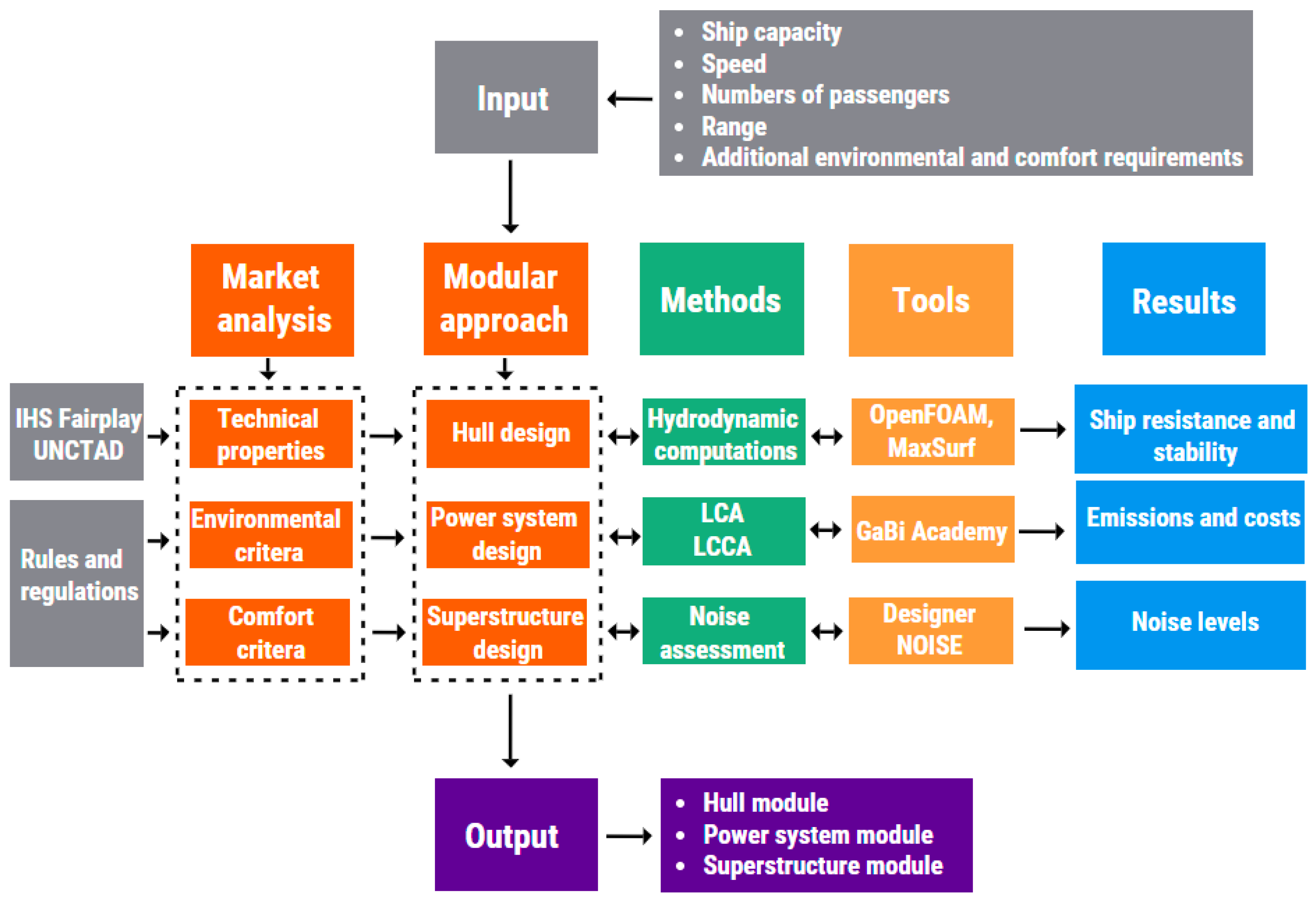
The developed methodology is schematically presented in Figure 2. The basic step includes an analysis of market needs and technical characteristics of existing vessels. Based on the design task that prescribes ship capacity, speed, range, and that might include additional requirements in terms of comfort or environmental friendliness, preliminary ship hull dimensions are determined and submitted to the preliminary resistance calculations and power needs prediction, by simplified methods. Within this investigation, the NavCad software is used, [18], but any other tool providing a quick estimation of the above quantities can be used. Comparative analysis of power needs with the power needs of similar ships available in the database is performed [19], and after the acceptable agreement is confirmed, a series of computations by computational fluid dynamics (CFD) tools are performed to obtain more reliable values. Depending on the power needs and allowable emissions, the most cost-effective power system module is selected. Similarly, depending on the target comfort level appropriate insulation of superstructure module is selected from a set of previously examined options.
2.2. Identification of Market Needs
2.2.1. Technical Properties of Existing Vessels in the Mediterranean
The first step in the analysis of the technical properties of existing vessels is to limit the range of vessels according to some criteria. There are different criteria according to which the ship can be designated either small or big, for instance, the length, capacity, gross tonnage, etc. In this investigation, the length is selected as the relevant quantity and technical properties of all passenger ships registered in the Mediterranean countries with a length below 100 m are taken into account from the IHS Fairplay database [19]. The rules that are applicable to small vessels treat the upper length boundary very differently. In this sense, according to the International Association of Classification Societies (IACS) small ships are those below 24 m, while depending on the context they can be up to 65 m in length (Bureau Veritas) or even up to 100 m (Det Norske Veritas), [20].
The analysis is conducted for 692 passenger vessels operating under the flag from one of the Mediterranean countries, built between 1999 and 2015. In Figure 3 ship particulars (length overall (LOA), draft, beam, and total installed power) are illustrated depending on the deadweight. It is obvious that the deadweight is not the most relevant quantity for passenger vessels, but it is regularly used because of its universal acceptance as a measure of ship size and because of its wide use in the reporting of statistical information.
Taking into consideration that the number of passengers is an important parameter for passenger ships the relationship between deadweight and number of passengers, and length overall and the number of passengers is illustrated in Figure 4.
Most of the vessels are equipped with fixed pitch propellers, Figure 5.
The above figures indicate that there is a relatively large scattering between ship dimensions, capacity and power systems among the analyzed vessels. Based on that, it is obvious that no unified solution for the ship hull and consequently power system and superstructure is possible. Therefore, a number of solutions for the mentioned modules are worked out.
2.2.2. Environmental Requirements
One of the most important environmental problems nowadays is global warming, which is caused by the increased concentration of anthropogenic Greenhouse Gases (GHGs) in the atmosphere. Their high concentration in the atmosphere forms a thick layer that prevents solar irradiation to scatter into outer space. Instead, due to the developed greenhouse effect, the Earth is warming up, which causes climate changes [21]. The Paris Agreement is an international treaty on climate change, which aims to keep the global temperature rise below 2 °C, in comparison to the pre-industrial level. This aim requires a sharp reduction in GHG emissions in each sector [22,23]. The major source of GHGs, as well other pernicious emissions (e.g., nitrogen oxides (NOX), sulfur oxides (SOX), particulate matter (PM), etc.), is fossil fuel combustion [24,25]. While GHG negatively affects the environment on a global scale, NOX, SOX and PM are local pollutants that negatively affect human health and cause the acidification of the environment [26,27].
In the maritime sector, SOX and NOX emissions are controlled based on the navigation area of a ship, i.e., whether the ship navigates in the global area, or it operates in Emission Control Areas (ECAs), in which emissions requirements are stricter than outside these areas [28]. While SOX emission is limited with the allowed content of sulfur in fuel, NOX emissions are regulated depending on the engine’s maximum operating speed [29].
In order to cope with the increasing GHGs emissions, the International Maritime Organization (IMO) set a goal according to which international shipping needs to reduce at least 50% of their released GHGs by 2050, compared to 2008. levels [30]. The IMO decarbonization strategy defines three levels of measures to achieve the required GHGs reduction goal: short-term, mid-term and long-term measures [31], Figure 6.
The short-term measure (2018–2023) refers to the Energy Efficiency Design Index (EEDI) and Ship Energy Efficiency Management Plan (SEEMP) as well as to the implementation of an operative measure of speed reduction. The mid-term decarbonization ambition (2023–2030), among others, includes a measure of increasing the energy efficiency for new and existing ships [31] and the Energy Efficiency Design Index of Existing ships (EEXI) that will be set in on force on 01 January 2023 [32]. Other mid-term measures are the implementation of Market-Based Measures (MBMs), such as emission pricing policy, and replacing conventional marine fuels with low-carbon fuels. For the long-term goal (2030 -), the implementation of zero-carbon fuels (hydrogen, ammonia, electricity, biofuels) and innovative emission reduction technology is required [31]. In addition to GHGs reduction, the replacement of fossil fuels with zero-carbon fuels will result in the reduction of other pernicious emissions. The ultimate goal of long-term ambition is zero-emissions powered ships by the end of the century. Decarbonization measures are summarized in Figure 7.
Within the existing ship power system design procedure, the environmental requirements that will be in force in the next 20–30 years need to be considered, and according to them, implement a proper power system. Since the Mediterranean Sea is currently investigated as a potential ECA [33], and there are some specific areas with local regulations, such as Marseille port in southern France which intends to become the Mediterranean’s 1st Fully Electric Port by 2025 [34], the ships of the future intended to operate in this area should be designed to cope with these requirements.
2.2.3. Comfort Requirements
Noise and vibration problems are inherent to all ships due to the number of engines and devices needed for their operation. The main noise sources are in ships are the following: main engine and generator sets, gearboxes, propellers, exhaust systems with engine room ventilation, auxiliary mechanisms, such as hydraulic systems, pumps, ventilation and air-conditioning systems, side thrusters, etc., Figure 8.
Passenger comfort is significant for the evaluation of the ship in the market and in the last decades it represents an important contractual point, subject to heavy penalties when the required comfort class is not fulfilled [36]. The comfort ratings for passenger accommodation differ from one classification society to another, and some selected values are shown in Table 1, where (1) reflects to high, while (3) denotes acceptable.
Reduction of noise can be generally achieved by active and passive methods, and in shipbuilding, passive methods like insulation, are common approaches.
To ensure that passengers are not disturbed by usual activities in the adjacent cabins, regular passive noise reduction methods are applied, i.e., fitting sound insulation. The comfort class criteria related to sound insulation (expressed in Weighted Sound Reduction Index or Rw) are shown in Table 2.
In [36] one can find the minimum added weight (expressed in kg/m2) to meet the sound indexes required between cabins and specific public spaces, according to the classification societies.
Class notations are assigned to vessels in order to determine applicable rule requirements for assignment and retention of class. In addition to the interior noise requirements described above, there is an additional class notation called SILENT, which refers to the ship’s environmental footprint (underwater noise emission).
Similarly to noise, classification societies have vibration standards associated with the comfort class notation, Table 3.
The rules do not cover every piece of structure or item of equipment onboard a vessel, nor do they cover operational elements. Activities that generally fall outside the scope of classification include such items as: design and manufacturing processes; choice of type and power of machinery and certain equipment; number and qualification of the crew or operating personnel; form and cargo carrying capacity of the ship and maneuvering performance; hull vibrations; spare parts; life-saving appliances and maintenance equipment. These matters may, however, be given consideration for classification according to the type of ship or class notations assigned. Det Norske Veritas, Lloyd’s Register and Bureau Veritas are taken as a reference because they were the first to develop Comfort Class notations, and therefore, are most common and widespread in the naval market with respect to this issue. In Table 3 the criteria (requirements) from the mentioned classification societies will be reviewed and compared.
One of the approaches of controlling and a better understanding of noise and vibration is the so-called Source–Path–Receiver model, Figure 9.
This theoretical model is used to examine the problem by breaking down the unit into three basic elements: the Source of noise and vibration, the conveying medium or so-called Path, and the Receiver. By recognizing these elements we can see that noise and vibration can be controlled by altering any of these three elements.
3. Materials and Methods
3.1. Hull Definition
Hydrodynamic analysis concerning a particular hull form can range from the simplest models involving only multiple ship parameters (e.g., length, breadth, draft, block coefficient, etc.) to the more complex direct numerical simulations. Numerical models can also differ significantly in their underlying fluid mathematical model. Regardless of the model, the most important factor is the accurate estimation of the ship resistance which leads to reliable estimations of the necessary engine power. In this work, a state-of-the-art numerical model in ship resistance is employed. The numerical model is based on the Computational Fluid Dynamics (CFD) with the Finite Volume (FV) space discretization. Viscosity and turbulence are included in the ship free-surface simulations. The simulations are performed for different speeds, thus obtaining the ship resistance curve for various Froude numbers. Simulations are performed by means of OpenFOAM [37] in a dedicated in-house naval library [38]. Computed ship resistance (Rt) is further used for the estimation of the required engine power as follows:
- -
- Added resistance from wind loads (10%) and appendages (10%) is estimated at 20% Rt total.
- -
- Effective propulsive power (PE) is computed for the selected ship speed (V).
- -
- Delivered power (PD) to the shaft is computed using the average fixed pitch propeller efficiency of 60%.
- -
- Brake power (PB) includes an additional 25% for various consumers (accommodation etc.) for passenger ships.
- -
- Engine MCR is usually set at 85% which leads to the estimation of installed engine power (PMCR).
Apart from the engine power estimation, an important aspect in ship design is the ship stability evaluation. Detailed stability calculations involve the entire ship structure and masses onboard along with the different loading conditions. In this work, only an illustrative example is given, so the center of gravity is approximated at an even keel inline with the center of buoyancy for a given condition. The vertical center of gravity is set at a percentage of ship height common to similarly built ships. The righting lever (GZ) curve is computed for a single load case and compared to the necessary stability criteria.
Results in Figure 4 and Figure 5 indicate that there is relatively high scattering between dimensions and total installed power of passenger ships in the Mediterranean. One of the reasons for this is the fact that considered data do not consider ship mission. Therefore, no single option can be selected in the definition of the hull module. For this reason, a generic hull model is employed with a variable stern, fore and mid-section depending on the project needs, Figure 10 shows the used hull modules which are adjusted accordingly and will be further defined depending on the design task. Within this paper, detailed results on the hull with a length of 45.0 m are included.
3.2. Power System
In this paper, the focus is put on the implementation of technical measures, hull design, but also on the replacement of conventional power systems with alternative ones. Future emission requirements force the shipping industry to move toward the implementation of alternative and cleaner fuels. Their application needs to be investigated from the environmental and economic points of view, where the baseline scenario is the currently used diesel-powered ship.
In order to establish a basis for the selection of appropriate power system modules, the environmental impact of a range of power systems with potential for applicability in passenger ships, Table 4, is analyzed by performing the Life-Cycle Assessment (LCA) by means of GaBi Academy software [39]. According to LCA guidelines of ISO 14,040 [40] and ISO 14,044 [41], performing LCA requires the definition of goal and scope of the assessment, functional unit, system boundary and inventory. In this paper, the LCA investigates the environmental eligibility of different alternative fuels implemented on a small passenger ship. A ton of released GHGs expressed as a unit of CO2-eq, represents the functional unit, while the inventory data is obtained from GaBi Academy databases. The system boundary is placed on the ship power system, where GHG emissions related only to the production of fuel (Well-to-Pump (WTP) phase, which includes processes from raw materials extraction and its transportation to the production facility, production of specific fuel and distribution to the ship), use of fuel (Pump-to-Wake (PTW) and manufacturing the main element of the system (Manufacturing (M) phase) are considered. For example, when analyzing a diesel-powered ship that serves as a baseline scenario, processes included in the LCA of this power system configuration are crude oil extraction and transportation to the production site, production of diesel and its distribution via tank trucks to the refueling station near the port, combustion of diesel in a diesel engine during ship operation, and manufacturing process of a diesel engine. The economic analysis is performed with the Life-Cycle Cost Assessment (LCCA), in which the investment, fuel and maintenance costs are investigated during the ship’s lifetime, i.e., 20 years of its exploitation [42].
3.3. Design of the Superstructure Module with Respect to Comfort Standards
Although the noise and vibration problems are usually considered simultaneously, the methods for their prediction and measurements are fundamentally different, because they are related to the completely different frequency ranges (noise is in the audible range above 30 Hz and is evaluated in decibels). The noise consists of two parts that are transmitted through two different transmission paths. In this sense, we the distinguish airborne and the structure borne paths, transmitted through the air and structure, respectively. Regularly, noise and vibration levels on board are measured at ship delivery, and if problems are detected, they should be remedied in order to achieve vessel compliance with the prescribed values. Despite a variety of noise abatement methods, the elimination of such problems at the delivery stage becomes rather expensive, and therefore, it is desirable to predict noise levels in the preliminary stage.
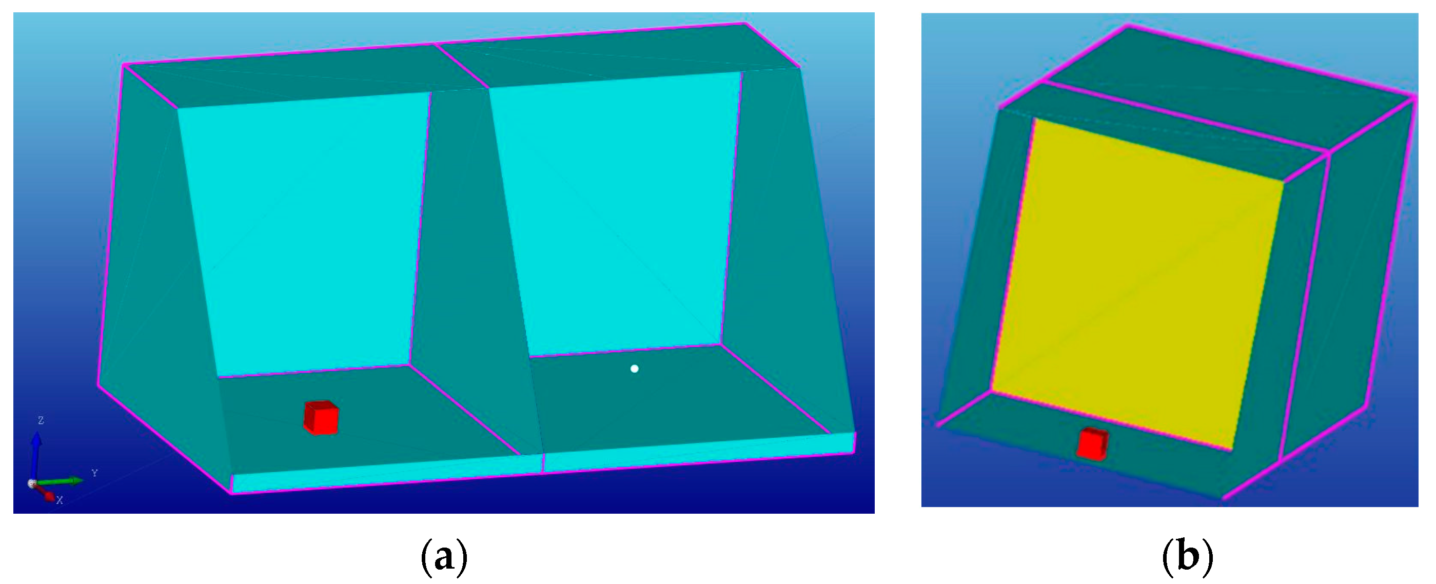
For noise assessment, the hybrid Statistical Energy Analysis (SEA) seems to be a reasonable choice, due to its simplicity and acceptable accuracy (particularly in the high frequency domain), [49]. Within the proposed approach passive noise reduction methods are applied, where mainly transmission paths are influenced, Figure 9. By means of the DesignerNOISE tool [50], series of passenger compartments, Figure 11, are investigated with different insulation materials and insulation thicknesses, where also the price is considered in order to provide guidance to the designer on the selection of the most appropriate one for the target comfort class, Figure 12.
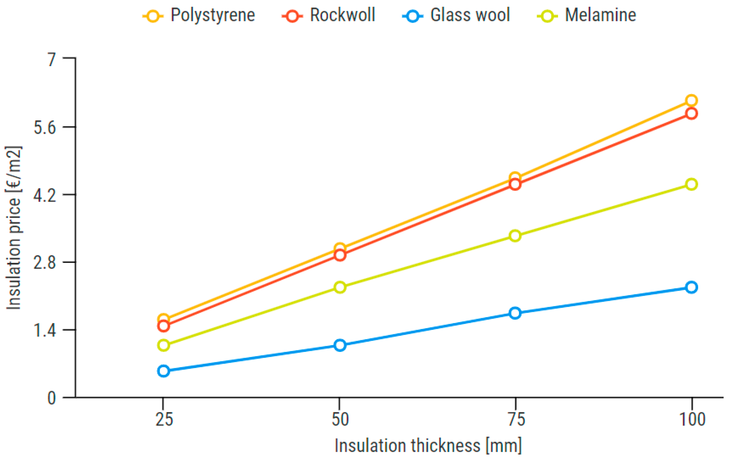
Prices of different materials are compared in, Figure 13, while comparison of the noise reduction potential f different materials is shown in Figure 14.
Besides noise, vibration also plays an important role in ship comfort. In the case of vibration, it is a generally accepted opinion that great benefits can be achieved if vibration reduction at the source is possible.
Interaction between the source represented and the receiver in case of vibration can be represented by the following equation:
where location l represents vibration velocity that is required by classification societies, while e specifies maximum excitation force induced by the engine. By implementing different technologies on the source (engine), its quality can be changed in order to mitigate and control vibration transmission. This is denoted as engine quality qE, and this quantity is directly related to the costs. Regularly, the engine excitation e is known from the producer, quality of the engine qE is represented as a percentage decrease of vibratory response (from 0.1 to 1.0), and the location l is defined as vibration velocity, and all that has to be done is to calculate the ship’s transfer function S. It is necessary to investigate the transfer function S in combination with different engines and their excitations that eventually leads to the same vibration velocity at a certain location at the ship. An illustration of this approach can be seen in Figure 15. Different comfort classes are represented by the comfort rating number (crn), where level 1 (yellow curve) is a better solution in comparison with 2 (blue curve) which represents the lowest comfort level. As can be noticed in Figure 15, if one wants to shift from crn = 3 to crn = 2 or 1, the engine quality should increase, which necessarily leads to additional costs.
4. Illustrative Example
Within this illustrative example, a pre-defined solution (concept-design) of a passenger vessel having LOA of 45.0 m and a capacity of 250 passengers is described.
4.1. Hydrodynamic Results
The ship hull analyzed in this study is a generic passenger ship model which satisfies an exemplary design task for length, breadth, number of passengers, etc. Parameters of the design task, i.e., ship particulars studied in this work, are given in Table 5.
Hydrodynamic results for resistance are computed in CFD for various ship speeds. An example of the simulation and computational mesh is shown in Figure 16. Results for the resistance curve are shown in Figure 17. Following the estimation method for the engine power explained in Section 3.2. the design speed power requirements can be calculated using the towing resistance force. The engine requirement for this hull design is equal to 840 kW. In order to take into account auxiliary power needs, the main ship power needs are increased by 25%.
Stability calculations are performed only for the preliminary design with a single loading condition (design condition). The ship superstructure is not defined in detail since it requires the design of the accommodation cabins, and the ship masses are not exactly specified at this design stage meaning that the ship center of gravity is only approximated. The righting lever curve is shown in Figure 18. Rules for the GZ curve are based on the IMO stability regulations for passenger ships and here only the basic rules for intact stability are checked and are satisfied.
4.2. Ship Power System Selection
The LCA and LCCA results of the investigated ship are presented in Figure 19 where D denotes diesel, E denotes electricity, M refers to methanol, H refers to hydrogen used in a Proton Exchange Membrane Fuel Cell (PEMFC), A refers to ammonia used in PEMFC, while BD refers to the biodiesel-diesel blend B20.
The results of the environmental and economic analysis indicated that full electrification with only a battery represents the most environmentally friendly and most cost-effective powering options among those considered.
4.3. Superstructure
Typical superstructure spaces are recommended to be insulated by glass wool since it offers the optimal solution for sound insulation with respect to weighted sound reduction index and the price. However, in a later design stage, when the ship is defined more precisely, the noise prediction should be performed again, Figure 20, and if noise prediction is encountered, special treatments should be performed.
It should be mentioned that LCA and LCCA assessments suggested electrification of the power system as a desirable option. This leads to excellent noise and vibration performance at the level of excitation source according to the Source–Path–Receiver model, Figure 9. By selection of environmentally friendly options of power systems, therefore, benefits for comfort level can be achieved.
5. Concluding Remarks
In this paper, the modular approach in the design of small passenger ships for the Mediterranean is illustrated, where the ship is virtually assembled from three predefined modules. The approach concept design phase, Figure 1, where there is still relatively high design uncertainty, i.e., the design task is not fully defined and there is design freedom to an alternate number of ship details. Modules of different environmental friendliness and habitability class are pre-defined and are interchangeable and adaptable to a series of ship hulls, forming concept designs of different quality and prices. As such, pre-defined solutions for ship hull, power system module and superstructure form a reasonable basis for the definition of detailed design requirements and based on that, the price breakdown can be made. Within the proposed approach, sophisticated analysis tools are integrated into the design loop. This approach particularly addresses environmental and comfort aspects, which nowadays belong to the most important issues in ship design.
The main findings of the paper can be summarized as follows:
- -
- Small passenger ships in the Mediterranean significantly differ in dimensions, power needs, propulsor type, etc., but most of them, however, utilize diesel-engine-powered propulsion,
- -
- Environmental and comfort criteria are important design aspects of future ships,
- -
- Environmentally-friendly solutions in the ship power system can result in comfort benefits,
- -
- Pre-defined solutions represent a useful tool for conceptual design, particularly for small shipyards which cannot invest huge resources in research and development,
- -
- Pre-defined solutions should be further optimized, as design freedom reduces, Figure 1,
- -
- The presented concept can be extended to an arbitrary number of modules (depending on the market needs), making the procedure more robust and faster to obtain pre-defined solutions.
The proposed approach did not include structural issues. Since global strength is regularly not a critical issue for smaller ships, structural issues should be considered within the local strength assessment, in further design stages where more information on the structure is known.
Although the procedure is focused on small passenger ships for the Mediterranean, the approach can be generalized by involving any other set of vessels in the fleet analysis and by considering a regulatory framework for other areas worldwide.
Author Contributions
Conceptualization, N.V., A.B. and M.P.; methodology, N.V. and A.B.; software, A.B., M.P. and I.J.; validation, A.B., M.P., and I.J.; formal analysis, N.V., A.B. and M.P.; investigation, N.V., A.B., M.P. and I.J.; resources, N.V.; data curation, I.J.; writing—original draft preparation, N.V.; writing—review and editing, A.B., M.P. and I.J..; visualization, A.B., M.P. and I.J.; supervision, N.V.; project administration, N.V.; funding acquisition, N.V. All authors have read and agreed to the published version of the manuscript.
Funding
This research was funded by the Croatian Science Foundation under the project Green Modular Passenger Vessel for Medi-terranean (GRiMM), (Project No. UIP-2017-05-1253). Maja Perčić, a Ph.D. student, is supported through the “Young re-searchers’ career development project–training of doctoral students” of the Croatian Science Foundation, funded by the European Union from the European Social Fund (ESF). Ivana Jovanović, a Ph.D. student is supported through the “Young researchers’ career development project–training of doctoral students” of the Croatian Science Foundation.
Institutional Review Board Statement
Not applicable.
Informed Consent Statement
Not applicable.
Data Availability Statement
Not applicable.
Conflicts of Interest
The authors declare no conflict of interest.
References
- Gelesz, P.; Karczewski, A.; Kozak, J.; Litwin, W.; Piatek, L. Design methodology for small passenger ships on the example of the ferryboat Motlawa 2 driven by hybrid propulsion system. Pol. Marit. Res. 2017, 24, 67–73. [Google Scholar] [CrossRef] [Green Version]
- Gianni, M.; Bucci, V.; Marino, A. System simulation as decision support tool in ship design. Proceedia Comput. Sci. 2021, 180, 754–763. [Google Scholar] [CrossRef]
- Zwaginga, J.; Stroo, K.; Kana, A. Exploring market uncertainty in early ship design. Int. J. Nav. Archit. Ocean Eng. 2021, 13, 352–366. [Google Scholar] [CrossRef]
- Andrews, D. A comprehensive methodology for the design of ships (and other complex systems). Proc. R. Soc. Lond. Ser. A Math. Phys. Eng. Sci. 1998, 454, 187–211. [Google Scholar] [CrossRef]
- Shields, C.P.; Singer, D.J. Naval design, knowledge-based complexity, and emergent design failures. Nav. Eng. J. 2017, 129, 75–86. [Google Scholar]
- Mckenney, T.A. An Early-Stage Set-Based Design Reduction Decision Support Framework Utilizing Design Space Mapping and a Graph Theoretic Markov Decision Process Formulation. Ph.D. Thesis, University of Michigan, Ann Arbor, MI, USA, 2013. [Google Scholar]
- Karczewski, A.; Kozak, J. Variant designing in the preliminary small ship design process. Pol. Marit. Res. 2017, 24, 77–82. [Google Scholar] [CrossRef]
- Ao, Y.; Li, Y.; Gong, J.; Li, S. An artificial intelligence-aided design (AIAD) of ship hull structures. J. Ocean Eng. Sci. 2021, in press. [Google Scholar] [CrossRef]
- Priftis, A.; Boulougouris, E.; Turan, O.; Atzampos, G. Multi-objective robust early stage ship design optimisation under uncertainty utilising surrogate models. Ocean Eng. 2020, 197, 106850. [Google Scholar] [CrossRef]
- Cook, R.L. The Impact of Modular Ship Design on the Life Cycle of Naval Vessel. Master’s Thesis, Massachusetts Institute of Technology (MIT), Cambridge, MA, USA, 1976. [Google Scholar]
- Erikstad, S.O. Modularisation in Shipbuilding and Modular Production, Innovation in Global Maritime Production; Norwegian University of Science and Technology (NTNU): Trondheim, Norway, 2009. [Google Scholar]
- Jollif, J.V. Modular ship design concepts. Nav. Eng. J. 1974, 86, 11–32. [Google Scholar] [CrossRef]
- Bertram, V. Modularization of Ships. Report within the Framework of Project “Intermodul” s/03/G IntermareC; ENSIETA: Brest, France, 2005. [Google Scholar]
- Tvedt, H. Modular Approach to Offshore Vessel Design and Configuration. Master’s Thesis, Norwegian University of Science and Technology (NTNU), Trondheim, Norway, 2012. [Google Scholar]
- Misra, S.C.; Sha, O.P. Modularization—A tool for production friendly ship designs. In Proceedings of the World Maritime Technology Conference, Mumbai, India, 21–24 January 2009. [Google Scholar]
- Damen. Available online: https://www.damenmodularbarges.com/ (accessed on 20 September 2019).
- Nam, T.; Mavris, D. Multi-stage reliability-based design optimization for aerospace system conceptual design. In Proceedings of the 49th AIAA/ASME/ASCE/AHS/ASC Structures, Structural Dynamics, and Materials Conference, Schaumburg, IL, USA, 7–10 April 2008. [Google Scholar] [CrossRef]
- NavCad. Available online: https://www.hydrocompinc.com/solutions/navcad/ (accessed on 1 December 2018).
- IHS. IHS Fairplay World Register of Ships—WROS Manual; IHS Global Inc.: Englewood, CO, USA, 2015. [Google Scholar]
- Available online: https://www.fsb.unizg.hr/kmb/100/110/kmb111.htm (accessed on 5 April 2017).
- United Nations Framework Convention Climate Change (UNFCCC). Climate Change Information Kit. Available online: https://unfccc.int/resource/iuckit/cckit2001en.pdf (accessed on 14 January 2021).
- Bataille, C.; Åhman, M.; Neuhoff, K.; Nilsson, L.J.; Fischedick, M.; Lechtenböhmer, S.; Solano-Rodriquez, B.; Denis-Ryan, A.; Stiebert, S.; Waisman, H.; et al. A review of technology and policy deep decarbonization pathway options for making energy-intensive industry production consistent with the Paris Agreement. J. Clean. Prod. 2018, 187, 960–973. [Google Scholar] [CrossRef] [Green Version]
- UNFCCC. The Paris Agreement. Available online: https://unfccc.int/process-and-meetings/the-paris-agreement/the-paris-agreement (accessed on 3 November 2021).
- Odeh, N.A.; Cockerill, T.T. Life cycle GHG assessment of fossil fuel power plants with carbon capture and storage. Energy Policy 2008, 36, 367–380. [Google Scholar] [CrossRef]
- Monteiro, A.; Russo, M.; Gama, C.; Borrego, C. How important are maritime emissions for the air quality: At European and national scale. Environ. Pollut. 2018, 242, 565–575. [Google Scholar] [CrossRef] [PubMed]
- Sofiev, M.; Winebrake, J.J.; Johansson, L.; Carr, E.W.; Prank, M.; Soares, J.; Vira, J.; Kouznetsov, R.; Jalkanen, J.-P.; Corbett, J.J. Cleaner fuels for ships provide public health benefits with climate tradeoffs. Nat. Commun. 2018, 9, 406. [Google Scholar] [CrossRef] [PubMed] [Green Version]
- Kim, T.; Chae, C. Environmental Impact Analysis of Acidification and Eutrophication Due to Emissions from the Production of Concrete. Sustainability 2016, 8, 578. [Google Scholar] [CrossRef] [Green Version]
- Chen, L.; Yip, T.L.; Mou, J. Provision of Emission Control Area and the impact on shipping route choice and ship emissions. Transp. Res. Part D Transp. Environ. 2018, 58, 280–291. [Google Scholar] [CrossRef]
- Emission Standards: IMO Marine Engine Regulations. Available online: https://dieselnet.com/standards/inter/imo.php#s (accessed on 1 November 2020).
- International Maritime Organization. Fourth IMO GHG Study-Final Report 2020. Available online: https://safety4sea.com/wp-content/uploads/2020/08/MEPC-75-7-15-Fourth-IMO-GHG-Study-2020-Final-report-Secretariat.pdf (accessed on 14 January 2021).
- DNV. Achieving the IMO Decarbonization Goals. Available online: https://www.dnv.com/expert-story/maritime-impact/How-newbuilds-can-comply-with-IMOs-2030-CO2-reduction-targets.html (accessed on 24 June 2021).
- DNV. Energy Efficiency Existing Ship Index (EEXI). Available online: https://www.dnv.com/maritime/insights/topics/eexi/index.html (accessed on 14 October 2021).
- Regional Marine Pollution Emergency Response Centre for the Mediterranean Sea. Med SOx ECA. Available online: https://www.rempec.org/en/our-work/pollution-prevention/hop-topics/med-eca/med-sox-eca-introduction (accessed on 27 October 2021).
- Offshore Energy. Marseille Fos—The Mediterranean’s 1st Fully Electric Port by 2025. Available online: https://www.offshore-energy.biz/marseille-fos-wants-to-be-mediterraneans-1st-fully-electric-port-by-2025/ (accessed on 21 October 2021).
- Tudor, H. Techno-Economic Assessment of New Marine Engine Development with High Noise and Vibration Performance. Master’s Thesis, UNIZAG FSB, Zagreb, Croatia, 2017. [Google Scholar]
- Blanchet, A. Comfort class and passenger ships. In Proceedings of the InterNOISE Conference, Nice, France, 27–30 August 2000. [Google Scholar]
- Weller, H.G.; Tabor, G.; Jasak, H.; Fureby, C. A tensorial approach to computational continuum mechanics using object oriented techniques. Comput. Phys. 1998, 12, 620–631. [Google Scholar] [CrossRef]
- Vukčević, V. Numerical Modelling of Coupled Potential and Viscous Flow for Marine Applications. Ph.D. Thesis, Faculty of Mechanical Engineering and Naval Architecture, University of Zagreb, Zagreb, Croatia, 2016. [Google Scholar]
- GaBi Academy. LCA Software. Available online: https://gabi.sphera.com/international/software/gabi-universities/gabi-academy/ (accessed on 12 December 2021).
- ISO 14040. Available online: https://www.iso.org/standard/37456.html (accessed on 5 January 2022).
- ISO 14044. Available online: https://www.iso.org/standard/38498.html (accessed on 5 January 2022).
- Perčić, M.; Vladimir, N.; Fan, A. Life-cycle cost assessment of alternative marine fuels to reduce the carbon footprint in short-sea shipping: A case study of Croatia. Appl. Energy 2020, 279, 115848. [Google Scholar] [CrossRef]
- Perčić, M.; Vladimir, N.; Fan, A. Techno-economic assessment of alternative marine fuels for inland shipping in Croatia. Renew. Sustain. Energy Rev. 2021, 148, 111363. [Google Scholar] [CrossRef]
- Perčić, M.; Vladimir, N.; Koričan, M. Electrification of inland waterway ships considering power system lifetime emissions and costs. Energies 2021, 14, 7046. [Google Scholar] [CrossRef]
- Perčić, M.; Ančić, I.; Vladimir, N. Life-cycle cost assessments of different power system configurations to reduce the carbon footprint in the Croatian short-sea shipping sector. Renew. Sustain. Energy Rev. 2020, 131, 110028. [Google Scholar] [CrossRef]
- Fan, A.; Wang, J.; He, Y.; Perčić, M.; Vladimir, N.; Yang, L. Decarbonising inland ship power system: Alternative solution and assessment method. Energy 2021, 226, 120266. [Google Scholar] [CrossRef]
- Ampah, J.D.; Yusuf, A.A.; Afrane, S.; Jin, C.; Liu, H. Reviewing two decades of cleaner alternative marine fuels: Towards IMO’s decarbonization of the maritime transport sector. J. Clean. Prod. 2021, 320, 128871. [Google Scholar] [CrossRef]
- International Renewable Energy Agency. A Pathway to Decarbonise the Shipping Sector by 2050. 2021. Available online: www.irena.org (accessed on 3 November 2021).
- Vladimir, N.; Bakica, A.; Ančić, I. Predictions of noise levels on board ships by hybrid SEA: Application to Ro-Ro passenger ship and self-propelled cutter suction dredger. In Proceedings of the 29th International Offshore and Polar Engineering Conference, Honolulu, HI, USA, 16–21 June 2019; pp. 4645–4651. [Google Scholar]
- Noise Control Engineering, LLC. Available online: http://noise-control.com/Designer_Noise_Help/ (accessed on 8 April 2021).
Figure 1.
Ship design and exploitation over time [3,17] (reproduced from [3] with permission of the Society of Naval Architects of Korea (SNAK), 2021).

Figure 2.
Methodology scheme.

Figure 3.
(a) Deadweight vs. Length overall, (b) Deadweight vs. Draft, (c) Deadweight vs. Beam, (d) Deadweight vs. Power.
Figure 3.
(a) Deadweight vs. Length overall, (b) Deadweight vs. Draft, (c) Deadweight vs. Beam, (d) Deadweight vs. Power.

Figure 4.
(a) Deadweight vs. Number of passengers, (b) Length overall vs. Number of passengers.

Figure 5.
Type of propulsors in the considered passenger vessels.

Figure 6.
The IMO strategy for the reduction of GHG emissions (reproduced from [31] with permission of Det Norske Veritas (DNV), 2022).
Figure 6.
The IMO strategy for the reduction of GHG emissions (reproduced from [31] with permission of Det Norske Veritas (DNV), 2022).

Figure 7.
Decarbonization measures.

Figure 8.
Main noise sources onboard [35].
Figure 8.
Main noise sources onboard [35].

Figure 9.
Source-Path-Receiver model.

Figure 10.
Hull modules are used within the proposed design procedure (fore, mid and stern modules).
Figure 10.
Hull modules are used within the proposed design procedure (fore, mid and stern modules).

Figure 11.
(a) Two adjacent compartments with noise source and receiver, (b) insulated bulkhead between passenger spaces.
Figure 11.
(a) Two adjacent compartments with noise source and receiver, (b) insulated bulkhead between passenger spaces.

Figure 12.
Noise reduction potential of different materials and specific prices.

Figure 13.
Comparative analysis of prices for different insulation materials.

Figure 14.
Noise levels at the receivers for different insulation materials.

Figure 15.
Vibratory response at passenger spaces depending on ship transfer functions and shifting to higher comfort level.
Figure 15.
Vibratory response at passenger spaces depending on ship transfer functions and shifting to higher comfort level.

Figure 16.
Computational mesh and free surface at ship design speed (V = 14 kn).

Figure 17.
Resistance curve computed in CFD.

Figure 18.
Righting lever curve (GZ) for design draft.

Figure 19.
A comparison of the LCA and LCCA of alternative fuels.

Figure 20.
Typical results of noise prediction for ship compartments.


Table 1.
Sound pressure levels (dB(A)) in passenger accommodation [36].
Table 1.
Sound pressure levels (dB(A)) in passenger accommodation [36].
| Location | DNV | BV | LR | |||||
|---|---|---|---|---|---|---|---|---|
| CRN(1) | CRN(2) | CRN(3) | 1 | 2 | 3 | 1 | 2 | |
| Top grade | 44 | 47 | 50 | 45 | 50 | 50 | 45 | 50 |
| Standard cabins | 49 | 52 | 55 | 50 | 55 | 55 | 45 | 50 |
| Public rooms | 55 | 58 | 62 | 55 | 60 | 65 | 55 | 60 |
| Open decks | 65 | 65 | 70 | 65 | 70 | 75 | 65 | 70 |
Table 2.
Comfort class criteria related to sound insulation Rw (dB) [36].
Table 2.
Comfort class criteria related to sound insulation Rw (dB) [36].
| Location | DNV | BV | LR |
|---|---|---|---|
| Between top grade cabins | 46 | 42 | 45 |
| Between standard cabins | 41 | 40 | 45 |
| Between cabins and standard public rooms | 55 | 55 | 55 |
| Between cabins and show rooms | 65 | 65 | - |
Table 3.
Maximum allowable values of vibration (mm/s) for selected spaces according to different classification societies.
Table 3.
Maximum allowable values of vibration (mm/s) for selected spaces according to different classification societies.
| DNV | LR | BV | ||||||||||||||
|---|---|---|---|---|---|---|---|---|---|---|---|---|---|---|---|---|
| Location | 1 | 2 | 3 | Av. | 1 | 2 | 3 | Av. | 1 | 2 | 3 | Av. | 1 | 2 | 3 | Av. |
| For ships less than 1600 GT | For ships ≥ 1600 GT | |||||||||||||||
| Passenger cabin, standard | 1.5 | 2.0 | 3.0 | 2.2 | 1.8 | 2.1 | 2.4 | 2.1 | 3.0 | 3.5 | 4.0 | 3.5 | 2.8 | 3.0 | 3.2 | 3.0 |
| Passenger cabin, superior | 1.5 | 1.5 | 2.0 | 1.7 | 1.5 | 1.8 | 2.1 | 1.8 | 1.7 | 2.0 | 2.2 | 2.0 | ||||
| Public spaces | 1.5 | 2.0 | 3.0 | 2.2 | 2.0 | 2.5 | 3.0 | 2.5 | 3.0 | 4.0 | 5.0 | 4.0 | 3.0 | 3.5 | 4.0 | 3.5 |
| Open deck recreation | 2.0 | 2.7 | 3.5 | 2.7 | 2.5 | 3.0 | 3.5 | 3.0 | ||||||||
| Crew cabins | 3.0 | 3.5 | 4.0 | 3.5 | ||||||||||||
| Mess rooms | 3.0 | 4.0 | 5.0 | 4.0 | 3.0 | 3.5 | 4.0 | 3.5 | ||||||||
| Offices | 3.0 | 4.0 | 5.0 | 4.0 | 3.0 | 3.5 | 4.0 | 3.5 | ||||||||
| Open public areas | 4.0 | 6.0 | 6.0 | 5.3 | ||||||||||||
| ECR, switchboard room | 4.0 | 6.0 | 6.0 | 5.3 | 4.0 | 5.0 | 6.0 | 5.0 | ||||||||
| Work places | 5.0 | 5.0 | 5.0 | 5.0 | 4.0 | 6.0 | 6.0 | 5.3 | 5.0 | 5.5 | 6.0 | 5.5 | ||||
| Ship Power System Configurations | |||
|---|---|---|---|
| Fuel | Simplified Scheme | Advantages | Drawbacks |
| Diesel |  |
|
|
| Electricity |  |
|
|
| Methanol |  |
|
|
| LNG |  |
|
|
| Hydrogen |  |
|
|
| Ammonia |  |
|
|
 | |||
| Biodiesel-diesel blend |  |
|
|
Table 5.
Ship particulars.
| Ship Particulars | ||
|---|---|---|
| Length overall (LOA) | 45.0 | m |
| Length waterline (LWL) | 42.3 | m |
| Breadth (B) | 9.0 | m |
| Draft (T) | 3.0 | m |
| Design speed (VS) | 14 | kn |
| Number of passengers | 250 | |
| Block coefficient (CB) | 0.45 | |
| Wetted surface (A) | 425.2 | m2 |
| Displacement (Δ) | 521.3 | t |
Publisher’s Note: MDPI stays neutral with regard to jurisdictional claims in published maps and institutional affiliations. |
© 2022 by the authors. Licensee MDPI, Basel, Switzerland. This article is an open access article distributed under the terms and conditions of the Creative Commons Attribution (CC BY) license (https://creativecommons.org/licenses/by/4.0/).
Share and Cite
MDPI and ACS Style
Vladimir, N.; Bakica, A.; Perčić, M.; Jovanović, I. Modular Approach in the Design of Small Passenger Vessels for Mediterranean. J. Mar. Sci. Eng. 2022, 10, 117. https://doi.org/10.3390/jmse10010117
AMA Style
Vladimir N, Bakica A, Perčić M, Jovanović I. Modular Approach in the Design of Small Passenger Vessels for Mediterranean. Journal of Marine Science and Engineering. 2022; 10(1):117. https://doi.org/10.3390/jmse10010117
Chicago/Turabian StyleVladimir, Nikola, Andro Bakica, Maja Perčić, and Ivana Jovanović. 2022. "Modular Approach in the Design of Small Passenger Vessels for Mediterranean" Journal of Marine Science and Engineering 10, no. 1: 117. https://doi.org/10.3390/jmse10010117
Note that from the first issue of 2016, this journal uses article numbers instead of page numbers. See further details here.