Image-Based Mechanical Balancing of Reservoir Volumes During Benchtop Flow Battery Operation
 Kirk P. Smith
 Charles W. Monroe
- Department of Engineering Science, University of Oxford, Oxford, United Kingdom
The long-term maintenance of stable redox-flow-battery performance requires a strategy to manage dynamic volume imbalances between electrolyte reservoirs. Even with ion-selective membranes as separators, bulk liquid exchange can occur within the reactor because of pressure differences across its positive and negative chambers. Disproportionation chemistries, wherein both electrolyte reservoirs have identical composition in the discharged state, tolerate species crossover reversibly. These make possible the use of low-cost porous separators, but such materials are more hydraulically permeable. Here we propose an approach to mitigate reservoir imbalance, using the nonaqueous vanadium acetylacetonate disproportionation chemistry as a test platform. We demonstrate a benchtop-scale control scheme, which relies on a camera that monitors reservoir volumes linked to a microcontroller that regulates the differential flowrate between flow streams. The balancing apparatus introduces no extra wetted components and enables real-time measurements of intra-cycle imbalance due to electroosmosis. All software and firmware is made available for community use.
1 Introduction
Several methods have been proposed for managing both differences in volumes and differences between average oxidation states between electrolyte reservoirs in redox flow batteries (RFBs). This article focuses on the volume-imbalance problem. The driving forces for bulk-electrolyte volume imbalance include mechanical pressure, osmotic pressure, and species-varying electroosmotic drag, as well as state-of-charge-dependent liquid properties such as density and viscosity, whose changes during cycling influence the previously mentioned phenomena. Any of these driving forces can result in bulk volume changes, either within a single cycle or cumulatively across several charge/discharge cycles. The latter cumulative effect can be negated through an appropriate volume balancing scheme. Practically, volume balancing eliminates a troubling (albeit reversible) source of capacity fade during cycling experiments, which helps to isolate factors that control other possible failure mechanisms.
Strategies to manage volume imbalance are summarized in Table 1. These include periodic and continuous external mechanical transfers of bulk electrolyte, continuous internal balancing of electrolyte by adjusting hydraulic pressure across the membrane (actively or passively), and mitigation of bulk imbalance by balancing average intra-cycle osmotic pressures with an additional solute.
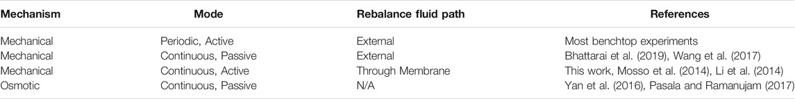
TABLE 1. Methods to manage bulk volume imbalance between reservoirs in redox flow batteries.
In this report we implement an image-based mechanical balancing method to maintain volume-balanced reservoirs during uninterrupted charge/discharge cycling by adjusting the hydraulic pressure across the cell membrane. As shown schematically in Figure 1, an external USB camera is used to measure the liquid volume (through heights h1 and h2) in both electrolyte reservoirs. The height difference is used as the input to a proportional–integral–derivative (PID) controller, which controls a pressure-modulating output. In the configuration reported here, this output is taken to be the difference in volumetric flowrates between the two pumps. Other implementations could use a control valve in either electrolyte flow path or the reservoir-headspace differential pressure as a PID control output, a methodology that could be enabled by an experimental setup similar to that of Li et al. (2014). The pumps researchers use for benchtop RFB experiments often allow some form of external speed-control input; the approach implemented here requires no additional hardware beyond a USB camera and a microcontroller, and avoids introducing additional wetted components in the flow path.

FIGURE 1. Overview of experimental setup for active balancing of electrolyte volumes in flow battery reservoirs. Pictures of (A) the experimental setup and (B) the level sensing image processing script during a flow battery experiment.
2 Materials and Methods
Acetonitrile (HPLC grade, Fisher, UK) and diethyl ether (puriss, Honeywell, Germany) were sparged with argon and dried over 4 Å molecular sieves (Sigma-Aldrich, USA). After sparging, acetonitrile was dispensed over an activated alumina column with a solvent purification system (Inert PureSolv, USA) before storage over molecular sieves. Both solvents were confirmed to be anhydrous using Karl-Fisher coulometry. All experiments were conducted in an argon-filled glovebox with <1.0 ppm O2 and H2O (PureLab, Inert Technologies, USA) using 0.1 M vanadium acetylacetonate (V(acac)3) in acetonitrile, with 0.3 M tetraethylammonium tetrafluoroborate (Sigma, 99%, UK) as a supporting salt. The V(acac)3 precursor (98%, Strem, UK) was recrystallized from hot acetonitrile and washed three times with diethyl ether before vacuum drying at ambient temperature while strictly avoiding exposure to ambient air.
The flow-cell construction was similar to that reported previously by Milshtein et al. (2016) with some minor modifications. PTFE tubing with 1/8″ OD and 1/16″ ID was used for all fluid connections, along with flanged low-pressure Cheminert® fittings (VICI, USA). A flow-through electrochemical cell configuration similar to that reported by Saraidaridis and Monroe (2019) was used, with porous 1/8″ thick carbon felt electrodes (Alfa Aesar, UK, no binder). The electrodes were vacuum dried for 24 h at 250°C before transfer to an argon-atmosphere glovebox. Celgard 4560 was used as a porous separator, and sealed between the carbon felt electrodes with laser-cut 1/8″ expanded PTFE gasket material (GORE, USA). Compression was approximately 70% of the initial thickness after using a torque wrench set to 25 in-lb on the four bolts of the cell. Resin-impregnated graphite (Graphitestore.com, USA) was used for current collectors contacting the carbon felts. All inlets and outlets were arranged to establish a counter-current fluid flow in the cell. One channel of an Ivium Octostat potentiostat was used as a battery cycler.
Chemically compatible diaphragm pumps (model FF-12, 1/4-28 fittings, DCB-4 wire control, FS 60X PEEK prefilter, KNF Neuberger, UK) were used in all experiments. A 24 V 1.25 A wall power supply was used to power the pumps. A Teensy 3.5 microcontroller received control input from a PC, and was used both to control pump duty cycles and monitor pump speeds. A USB webcam (Logitech, C505E, 2MP) was aimed at the reservoirs and video output was processed on the PC using the OpenCV Python library (Bradski, 2000) to determine reservoir levels. Various Python scripts facilitated communication and data logging between the PC, USB camera, and microcontroller. Relevant firmware/software files can be found on GitHub at https://github.com/kirkpsmith/rfb-volume-balancing.
After consideration of other techniques for measuring liquid levels in the reactant reservoirs, image-based monitoring was chosen both because of its simplicity and because its contact-free nature avoided chemical compatibility requirements. To facilitate sensing of reservoir levels, transparent reservoirs (or an external sight tube) are required, and the electroyte must be a different color from the background reservoir/headspace at every state of charge. (NB: Sensing of optically clear liquids could be possible with extension of the sensing code.) The liquid-level sensor functions by first prompting the user to select sensing areas from the camera feed that correspond to virtual sight tubes: the user draws a rectangular box on the image for each reservoir, with the stipulation that the box contains both electrolyte and headspace over an adequate sensing range. These virtual sight tubes are then calibrated to a known height from any external volumetric graduations on the reservoirs, or from prior knowledge of the vessel’s height–volume relationship. Here, the reservoirs were cylindrical vials, so a constant horizontal cross-section was assumed, such that the fluid volume in the reservoirs tracked linearly with the liquid-surface height.
Binary image thresholding is used to convert each frame from the camera into black and white. Further image processing manipulates the sensed area to remove any irregularities, such as those that arise from droplets adhered on the reservoir walls. The height of the processed sensed area is then converted to a volume using the reference height–volume relationship and time-averaged over a 60 s period to filter the effects of liquid-level fluctuations from stirring, or from electrolyte splashing in from the cell outlet tubing or reservoir inlet tubing. Upon cell assembly, when a known volume of electrolyte is evenly split between reservoirs, the level sensor calibrates itself against this known volume so that absolute volume measurements can be made that incorporate the piping and reactor-chamber volumes. This enables tracking of both relative changes between reservoirs and the absolute volume contained in both reservoirs, to monitor electrolyte leakage and solvent evaporation, as well as state-of-charge dependent volume changes of individual reservoirs.
The 60 s time-averaged signal of the real-time volume of each reservoir is subsequently averaged over a time period corresponding to twice the expected cycle length before being sent to the PID controller. This last constraint prevents the controller from responding to any intra-cycle volume imbalances, such as those induced by electroosmosis of solvent, while allowing it to respond to cumulative changes that arise between cycles.
The microcontroller is programmed to maintain a minimum flowrate in each half-cell. To force volume transfer that compensates for inter-cycle imbalancing, the pump speeds are adjusted by the PID controller beyond this minimum flowrate. The input to the PID controller is the volume difference between reservoirs, and the output is the applied difference between the pump speeds. The signs of the gains in the PID controller are such that if the positive reservoir has more electrolyte than the negative reservoir, the speed of the pump on the positive electrolyte flow stream will increase, increasing the hydraulic pressure in the positive half-cell and driving electrolyte back to the negative reservoir. Alternatively, the pump speed is increased on the negative flow stream if the negative reservoir contains more electrolyte than the positive reservoir. In both cases, the pump corresponding to the reservoir with the lower level of electrolyte is maintained at the predetermined minimum flowrate while the other pump operates at a higher speed, responding to the PID output control signal to rectify imbalance. The time-averaged input signal and the integral term of the controller can create some overshoot and phase lag between the input and output, but this is necessary to avoid oscillations. The derivative term was always set to zero in the present experiment.
Once the PID controller is properly tuned, unless the major and minor frictional losses are perfectly matched between half-cell fluid paths, there will be some steady-state flowrate difference between the positive and negative half-cells. If strict control of the rates of convection on either side of the reactor is desired, this difference can be avoided by designing the system differently. For example, one could maintain equal flowrates on both sides of the reactor with positive-displacement pumps, but regulate the pressure drop across the separator by using the PID controller to adjust the aperture of a needle valve in line with or a clamp around the flexible piping.
For tests of the control system, 10 ml of electrolyte was evenly split between two 10 ml glass vials sealed with rubber septa, making for 5 ml of electrolyte on each side of the flow-battery reactor. A piece of 1/8″ PTFE tubing was used to connect the headspaces of the sealed vials, to equilibrate their pressures and make it easier for the pumps to promote rebalancing through speed adjustment. Charge/discharge cycling took place with a current density of 20 mA/cm2 and base flowrate of 20 ml/min. A 10 s hold at open circuit was performed between charge and discharge half-cycles. The high-voltage cutoff for the first 10 cycles was 2.2 V; subsequent cycles applied a constant charging current for 280 s, which nearly matched the initial 2.2 V cutoff half-cycle lengths. This change to a coulomb-counting charge step accounted for slight increases in overpotential that arose from gradual solvent evaporation or electrolyte leakage, effects which can cause the apparent open-circuit potential to drift. The lower voltage cutoff was always maintained at 1.4 V. The level sensing and PID control scripts were initiated as cycling started, and controller gains and sampling windows were tuned manually until a steady state was established. Then, the PID control system was shut off and flow conditions returned to the base flowrate.
3 Results
Cycling results from this active balancing demonstration are shown in Figure 2. Representative voltage profiles for several charge/discharge cycles are shown in Figure 3.
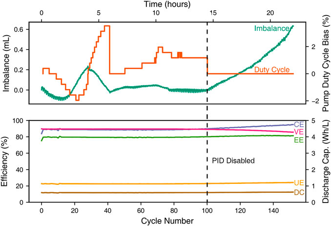
FIGURE 2. Top: volume imbalance between the nominally 5 ml electrolyte volumes and PID pump-speed output control signal, expressed as a duty cycle bias, as functions of time while cycling. Bottom: Cycle efficiencies (coulombic, CE; voltaic, VE; energy, EE; and utilization, UE) as well as discharge capacity (DC) as functions of cycle number.

FIGURE 3. Voltage profiles of charge/discharge cycles during active balancing. A 10 s open-circuit hold is performed between every charge and discharge step to track state-of-charge drift.
For the first 100 cycles, coulombic efficiency is 88.7 ± 0.6%, voltaic efficiency 89.5 ± 0.1%, energy efficiency 79.4 ± 0.5%, and utilization efficiency 22.6 ± 0.1%. Utilization efficiency is defined as the percentage accessed on discharge of the maximum theoretical charge capacity in solution, derived from the active-species concentration and the volume initially contained in each reservoir.
Imbalance versus applied pump duty cycle is shown at the top of Figure 2. The diaphragm pumps used for the experiments take a 0–100% duty cycle to determine pump speed. The pumps were initially set to run at 20 ml/min, which was calibrated to be a 36% duty cycle for the pump/cell/discharged-electrolyte combination. The right y-axis reflects the bias (i.e., relative change) in pump duty cycle from the base value of 36%. A positive value reflects an increase in speed of the left, negative pump and vice versa. The discrete steps in the duty cycle are reflective of the output of the PID control script, which is constrained by the microcontroller’s 8-bit digital-to-analog converter.
A closer look at intracycle imbalance during particularly stable cycling period is presented in Figure 4. The Figure shows both the net volume imbalance and the volumes of the individual reservoirs.

FIGURE 4. Intracycle imbalance and individual reservoir volumes during the stable, balanced cycling period achieved after 12 h of running with the control scheme.
4 Discussion
The first phenomenon observable in the cycling data is the increased stability gained when switching from a high voltage cutoff to a coulomb-based cutoff after 10 cycles. Because the slope of the Nernstian charging plateau is relatively flat, the amount of electrical charge passed during the charging step can be fairly sensitive to millivolt changes in overpotential between cycles, which may arise from various sources, including noise. Using a charge-based cutoff avoids this issue and eliminates otherwise premature end conditions for the charging step.
The controller takes some time to tune manually and also to stabilize. As can be seen from Figure 2, setpoint overshoot causes decaying oscillations in the volume imbalance when the control system is first started up. After about 6 h, a relatively steady level of imbalance is reached. Notably, even during the initial transient, the decaying fluctuations in the reservoir volumes have a nearly imperceptible effect on efficiency metrics and the accessible capacity, also shown in Figure 2.
Figure 3 presents the fairly consistent charging and discharging voltage profiles observed over the almost 24-hour-long experiment. It also shows that there is minimal oxidation-state drift, since the open-circuit potentials after the charging steps remain relatively constant. The first cycle is longer than the others because the experiment begins with a fully discharged electrolyte. After the balancing scheme is disabled, there is some decrease in voltaic efficiency, seen in Figure 3 as an increased overpotential during charge for cycles 125 and 150. This increase could owe to the volume imbalance developed after the balancing system was shut off, or other possible factors, such as solvent evaporation, which are beyond the scope of this study.
The level-sensing information can be used to examine intra-cycle imbalance, as shown in Figure 4. The peak-to-peak amplitude of this volume swing is approximately 30 µL (0.6% of the reservoir volume). This imbalance could arise for various reasons, not limited to a combination of electroosmotic drag, variable density of the electrolytes with state of charge, or changes in relative viscosity between half-cells changing the mechanical pressure difference across the cell at a given flowrate and causing bulk permeation of electrolyte across the separator.
No electrolyte leakage was observed anywhere on the exterior of the experimental apparatus, but Figure 4 does show a slow decrease of the absolute values of both electrolyte volumes. This slow loss can be attributed to solvent evaporation, which is believed to happen at similar rates in both reservoirs. Even in the presence of net solvent loss, the PID controller, which observes only the difference between reservoir volumes, should compensate for any changes in half-cell fluid properties as they become more concentrated over time. Notably, the controller’s ability to track this slow decrease in total electrolyte volume provides quantitative guidance for manual or automated solvent top-up procedures.
This pump-based reservoir volume-balancing approach is imaginable at scale, where it would continue to enjoy the benefits of its avoidance of additional wetted components and its minimal hardware cost. At any state-of-charge above 0%, there will likely be non-negligible transmembrane osmotic pressure owing to the difference in chemical activity between the charged electrolytes on either side. As such, depending on the average state-of-charge, the average applied pump-speed difference will be nonzero. This may result in better mass transfer at one electrode at the expense of increased pumping cost. A control valve could be introduced instead, and while this may allow for equal flowrates, it would result in a similar pumping cost due to the minor loss from the valve, with one electrode missing out on a potential mass-transfer enhancement. If electrolyte properties are well understood, the most efficient solution to maintain balanced reservoirs with minimal pumping penalty may be the careful use of a draw solute to balance the average osmotic transmembrane pressure, similar to the strategy used by Yan et al. (2016) and Pasala and Ramanujam (2017). With a symmetric electrolyte configuration (identical discharged half-cell electrolyte compositions, such as in the present study), however, the draw solute would be expected to attain identical concentrations in each reservoir, complicating matters. In any case, pump-based volume balancing can be used as a backup technique for excursions outside the intended osmotic-pressure range.
If a cell chemistry’s nonideality is such that it consistently exerts transmembrane osmotic pressure towards one half-cell (positive or negative), a passive balancing solution may be to hermetically seal the half-cell reservoir possessing the lower osmotic pressure, so that it builds up static pressure head opposing the osmotic pressure difference. Essentially, this makes the lower-osmotic-pressure half-cell reservoir contain zero headspace. Whether or not this is feasible at scale depends on the cost of hermetically sealing the exterior volume of a suitable reservoir to handle excursions above ambient pressure (by the amount of the osmotic pressure difference and any volume expansion). Turning one reservoir into a pressure vessel and/or adding an expansion tank may introduce unnecessary cost to a large-scale system, however.
5 Conclusion
We have demonstrated a straightforward approach to achieve volume-balanced reservoirs on the benchtop scale using the nonaqueous vanadium acetylacetonate redox-flow-battery chemistry as a test bed. The approach uses readily accessible hardware and software, which permit further development by the research community. Maintaining stable electrolyte volumes during cycling allows for further deconvolution of the competing failure modes encountered in flow-battery research.
Data Availability Statement
The original contributions presented in the study are included in the article; further inquiries can be directed to the corresponding author.
Author Contributions
KS and CM designed the research. KS performed experiments and drafted the manuscript. CM revised the manuscript and supervised. Both authors contributed to the article and approved the submitted version.
Funding
This work was supported by the UK EPSRC, within the ISCF Materials Research Hub for Energy Conversion, Capture, and Storage (M-RHEX), grant no. EP/R023581/1.
Conflict of Interest
The authors declare that the research was conducted in the absence of any commercial or financial relationships that could be construed as a potential conflict of interest.
Publisher’s Note
All claims expressed in this article are solely those of the authors and do not necessarily represent those of their affiliated organizations, or those of the publisher, the editors and the reviewers. Any product that may be evaluated in this article, or claim that may be made by its manufacturer, is not guaranteed or endorsed by the publisher.
References
Bhattarai, A., Wai, N., Schweiss, R., Whitehead, A., Scherer, G. G., Ghimire, P. C., et al. (2019). Vanadium redox flow battery with slotted porous electrodes and automatic rebalancing demonstrated on a 1 kW system level. Appl. Energ. 236, 437–443. doi:10.1016/j.apenergy.2018.12.001
Bradski, G. (2000). The OpenCV library. Dr. Dobb’s J. Softw. Tools. Available at: https://github.com/itseez/opencv.
Li, B., Luo, Q., Wei, X., Nie, Z., Thomsen, E., Chen, B., et al. (2014). Capacity Decay Mechanism of Microporous Separator-Based All-Vanadium Redox Flow Batteries and its Recovery. ChemSusChem 7, 577–584. doi:10.1002/cssc.201300706
Milshtein, J. D., Barton, J. L., Darling, R. M., and Brushett, F. R. (2016). 4-acetamido-2,2,6,6-tetramethylpiperidine-1-oxyl as a model organic redox active compound for nonaqueous flow batteries. J. Power Sourc. 327, 151–159. doi:10.1016/j.jpowsour.2016.06.125
Mosso, R., Durairaj, S., Sha, J., and Meyers, J. (2014). Pressure balancing of electrolytes in redox flow batteries. US: U.S. Patent No US20140057141A1.
Pasala, V., and Ramanujam, K. (2017). On In-situ Redox Balancing of Vanadium Redox Flow Battery Using D-Fructose as Negative Electrolyte Additive. ChemistrySelect 2, 720–727. doi:10.1002/slct.201601417
Saraidaridis, J. D., and Monroe, C. W. (2019). Nonaqueous vanadium disproportionation flow batteries with porous separators cycle stably and tolerate high current density. J. Power Sourc. 412, 384–390. doi:10.1016/j.jpowsour.2018.11.058
Wang, K., Liu, L., Xi, J., Wu, Z., and Qiu, X. (2017). Reduction of capacity decay in vanadium flow batteries by an electrolyte-reflow method. J. Power Sourc. 338, 17–25. doi:10.1016/j.jpowsour.2016.11.031
Keywords: flow battery, balancing, reservoir control, electrolyte management, image-based volume measurement
Citation: Smith KP and Monroe CW (2021) Image-Based Mechanical Balancing of Reservoir Volumes During Benchtop Flow Battery Operation. Front. Chem. Eng. 3:748865. doi: 10.3389/fceng.2021.748865
Received: 28 July 2021; Accepted: 28 September 2021;
Published: 26 October 2021.
Edited by:
Anna Hankin, Imperial College London, United KingdomReviewed by:
Evangelos Kalamaras, University of Warwick, United KingdomFranky Esteban Bedoya-Lora, University of Antioquia, Colombia
Copyright © 2021 Smith and Monroe. This is an open-access article distributed under the terms of the Creative Commons Attribution License (CC BY). The use, distribution or reproduction in other forums is permitted, provided the original author(s) and the copyright owner(s) are credited and that the original publication in this journal is cited, in accordance with accepted academic practice. No use, distribution or reproduction is permitted which does not comply with these terms.
*Correspondence: Charles W. Monroe, charles.monroe@eng.ox.ac.uk