Article

A Cyber-Physical System for Girder Hoisting Monitoring Based on Smartphones

1
State Key Laboratory of Coastal and Offshore Engineering, Dalian University of Technology, Dalian 116000, China
2
School of Civil Engineering, Dalian University of Technology, Dalian 116000, China
3
School of Electronic Science and Technique, Dalian University of Technology, Dalian 116000, China
4
School of Software Technology, Dalian University of Technology, Dalian 116000, China
*
Author to whom correspondence should be addressed.
Sensors 2016, 16(7), 1048; https://doi.org/10.3390/s16071048
Submission received: 18 May 2016 / Revised: 23 June 2016 / Accepted: 4 July 2016 / Published: 7 July 2016
(This article belongs to the Special Issue New Paradigms in Cyber-Physical Social Sensing)

Abstract

:
Offshore design and construction is much more difficult than land-based design and construction, particularly due to hoisting operations. Real-time monitoring of the orientation and movement of a hoisted structure is thus required for operators’ safety. In recent years, rapid development of the smart-phone commercial market has offered the possibility that everyone can carry a mini personal computer that is integrated with sensors, an operating system and communication system that can act as an effective aid for cyber-physical systems (CPS) research. In this paper, a CPS for hoisting monitoring using smartphones was proposed, including a phone collector, a controller and a server. This system uses smartphones equipped with internal sensors to obtain girder movement information, which will be uploaded to a server, then returned to controller users. An alarming system will be provided on the controller phone once the returned data exceeds a threshold. The proposed monitoring system is used to monitor the movement and orientation of a girder during hoisting on a cross-sea bridge in real time. The results show the convenience and feasibility of the proposed system.

Graphical Abstract

1. Introduction

Cyber-physical systems (CPS) have recently become an important research field these years [1,2]. It’s a multidisciplinary field involving physics, communication, computation, control, and so on. CPS tries to connect the physical world and information world. It not only serves as the ears and eyes of the information with sensors, but also serves as the hand to change the mode of the physical activity and provide convenient lives for people [3,4]. There have been many CPS applications [5,6], such as medical devices and systems, assisted living, traffic control and safety, advanced automotive systems, process control, distributed sensing command and control, smart structures, autonomous electric vehicle [7] and so on.
In recent years, smartphones have become popular on an unprecedented scale and can now be used as effective scientific tools. With an operating system, communication system and built-in sensors, they have already been applied to cyber-physical systems [8], including human health monitoring [9], vehicle maintenance services [10] and accident detection [11], motivation recognition [12,13,14,15], and structural health monitoring (SHM) [16,17,18,19,20,21,22,23,24]. Authors have also applied smartphones in the SHM field [25], in uses such as cable force monitoring [26,27,28], displacement monitoring [29], and earthquake rescue [30,31], etc. These applications allow the people to participate in the structural health perception process through the mobile phone and help people take corresponding measures to be safer.
During the construction of cross-sea bridges, each operation faces challenges due to the complexity of the environment, particularly in terms of hoisting [32]. The girders that require hoisting into place are typically bulky and heavy, and the crane performing the hoisting operation is floating on the sea and is thus significantly affected by waves and winds. Therefore, offshore construction is considerably more difficult than construction on land. The hoisting of a heavy structural element is critical to the entire project construction plan; any accident during a hoisting operation could result in considerable property loss or casualties and affect the construction schedule of the entire project. To ensure that a hoisting operation can be completed safely, the orientation and movement of a girder should be monitored in real time, and corresponding measures should be taken based on monitoring results. For monitoring the girder hoisting process, the total station is employed in the traditional method. However, it’s always influenced by landform; some parts can’t be measured because of the block and it’s difficult to place it on the site construction at sea. Thus, a new sensing and monitoring method, which calls for fewer restrictions for landform and more convenient operations, is of great value. As previously mentioned, smartphones represent a mobile technology of the cyber-physical social system, with advantages of lower cost, convenience, easy operation, that may be useful for girder hoisting monitoring. We highlight the features and contributions of our paper as follows:
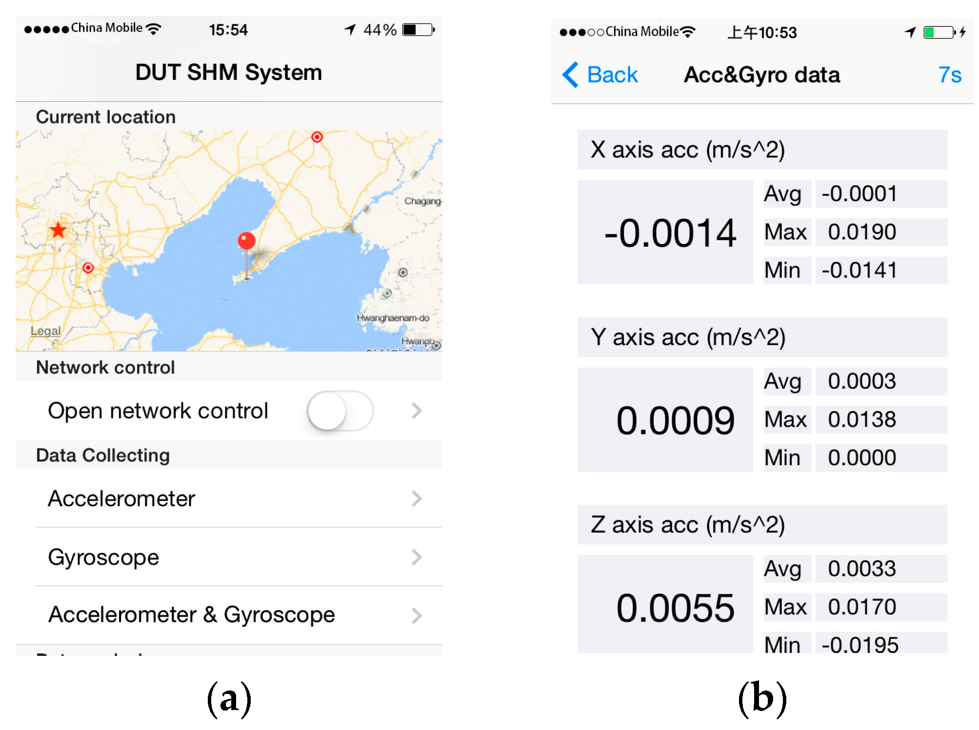
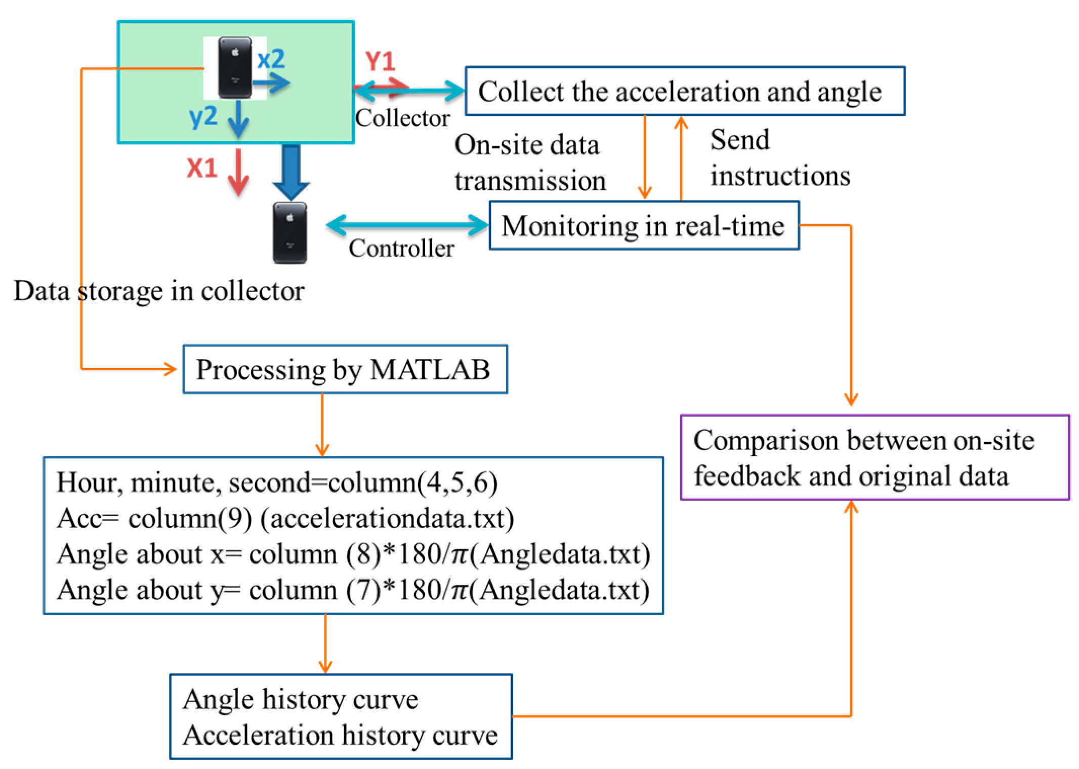
  • An iPhone-based monitoring system is developed; this system uses smartphones equipped with internal sensors to obtain girder movement information, which will be uploaded to a server, and then return to controller users.
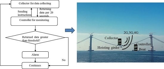
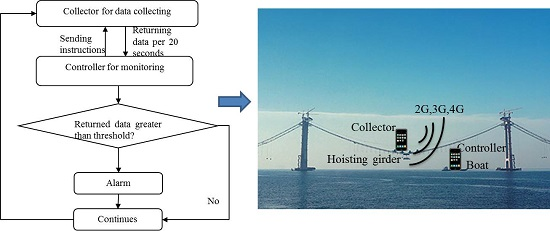
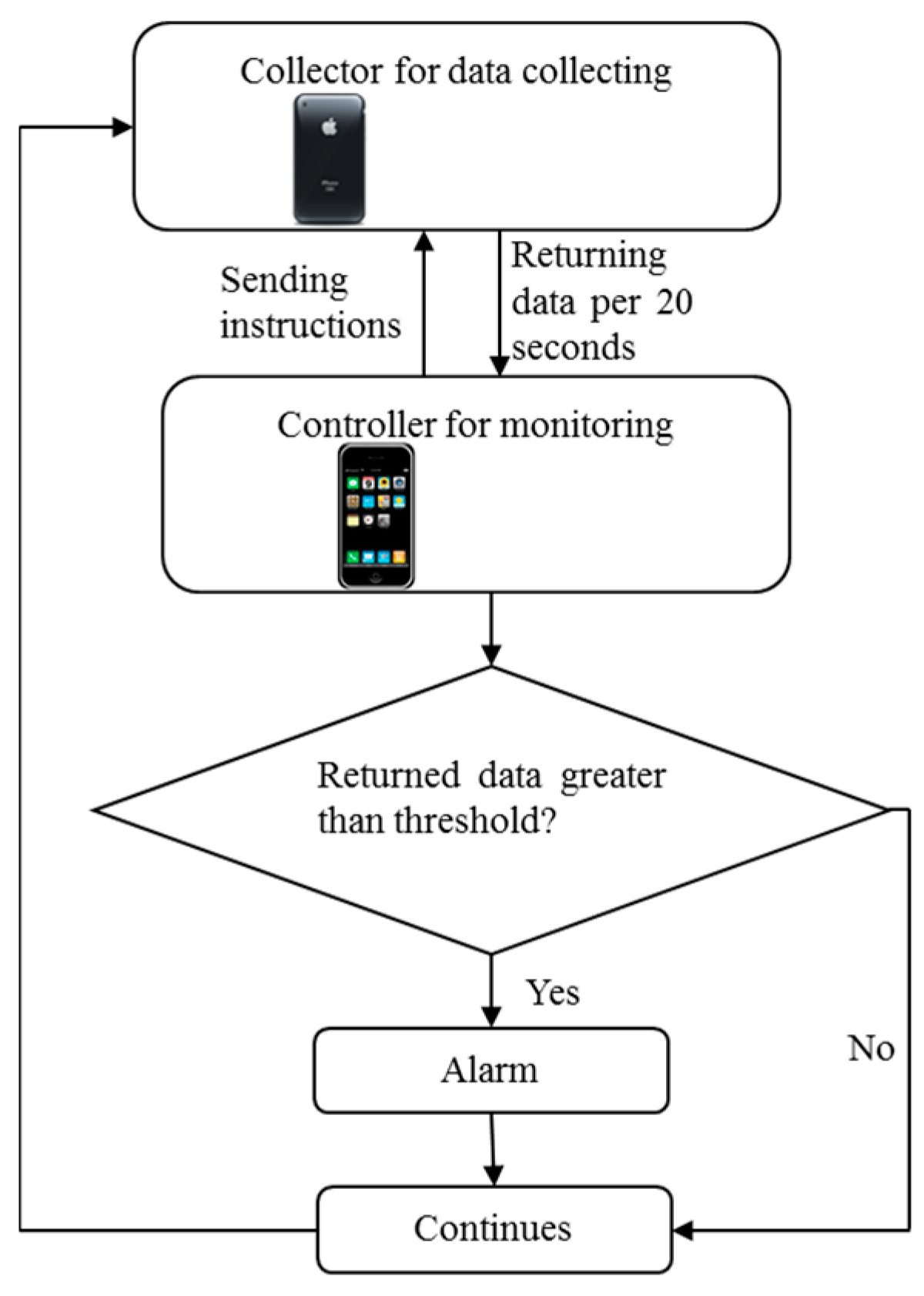
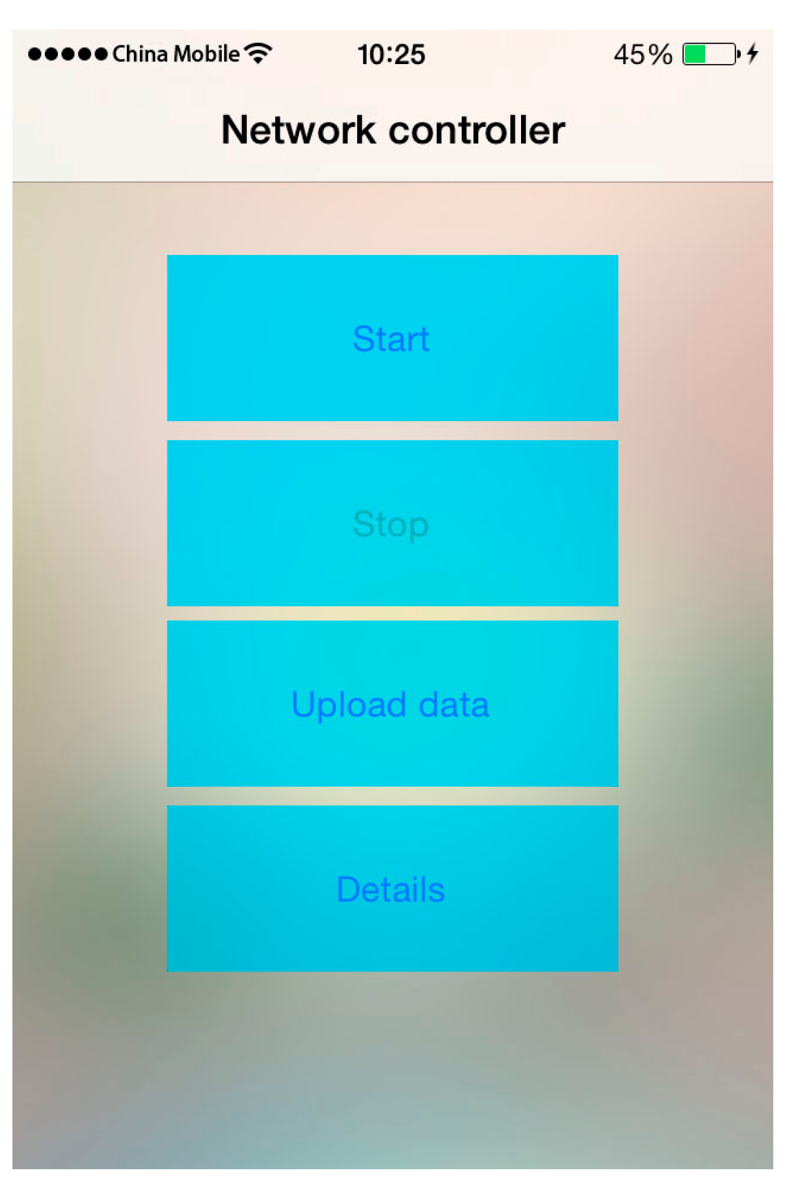
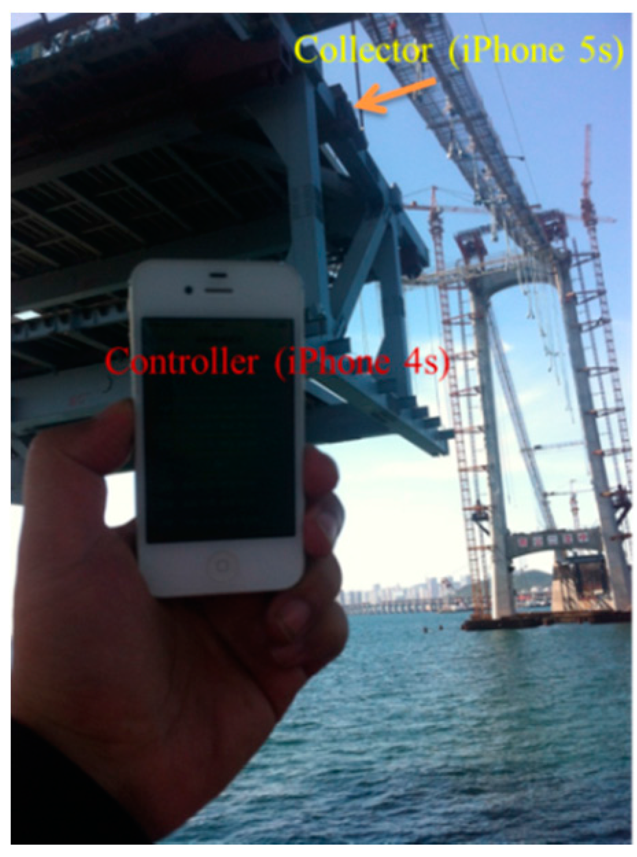
  • The system consists of a controller and collectors. The controller can send instruments to the collector to control the state of collector, it can also receive monitoring and warning information from the collector in real-time.
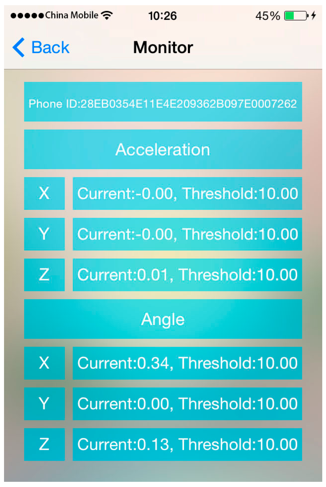
  • An alarming function is designed, and once the returned data exceeds a threshold, an alarm will appear on the controller iPhone.
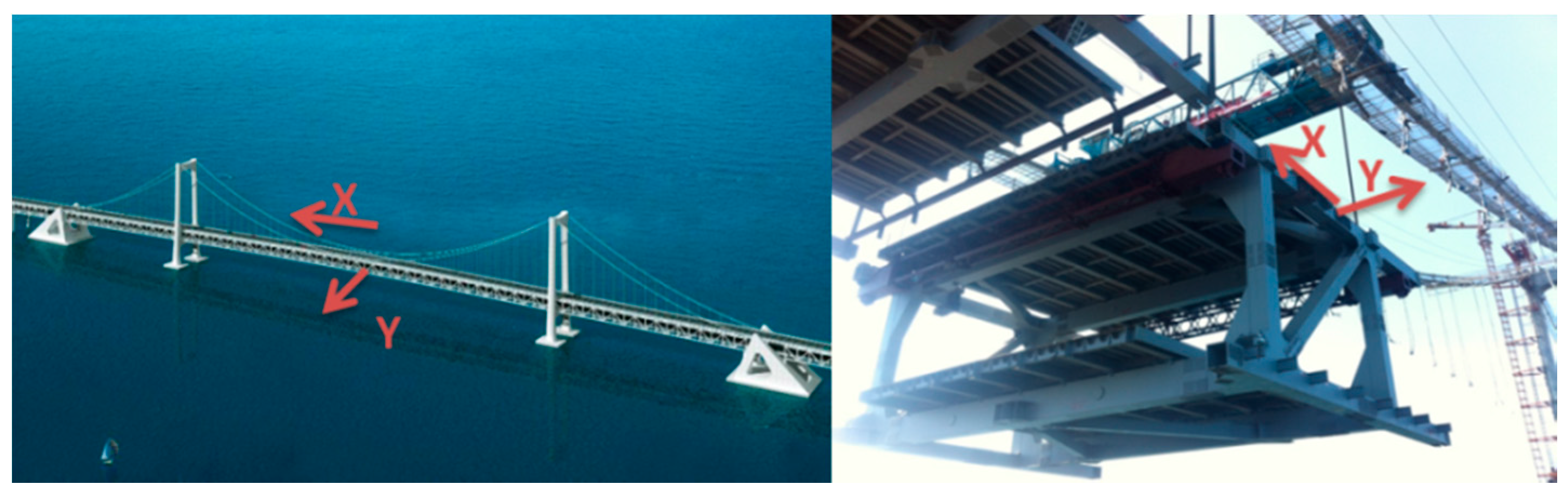
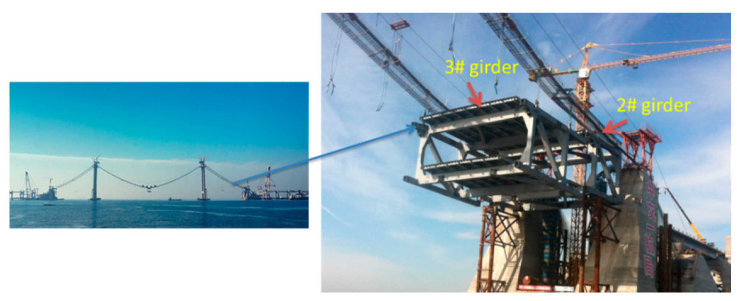
  • The proposed system is used to monitor the movement and orientation of a girder during hoisting on a cross-sea bridge. The site monitoring results validate the data acquisition, data transmission, commands control and alarming functions. This CPS using smartphones and wireless networks in hoisting monitoring can provide more field conditions for operators and help them take corresponding measures to ensure safety.
The remainder of the paper is organized as follows: Section 2 describes the offshore bridge which girder hoisting need to be monitored. Section 3 gives the architecture of the hoisting monitoring system, and calibrates the angle measured by the iPhone. Section 4 and Section 5 show the monitoring test on the side-span and middle-span respectively. Section 6 concludes this paper.

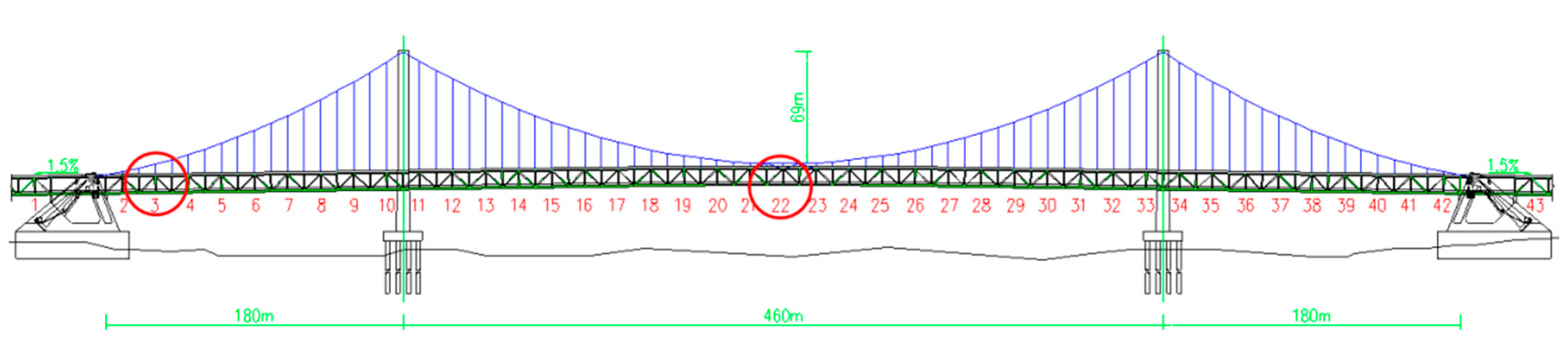
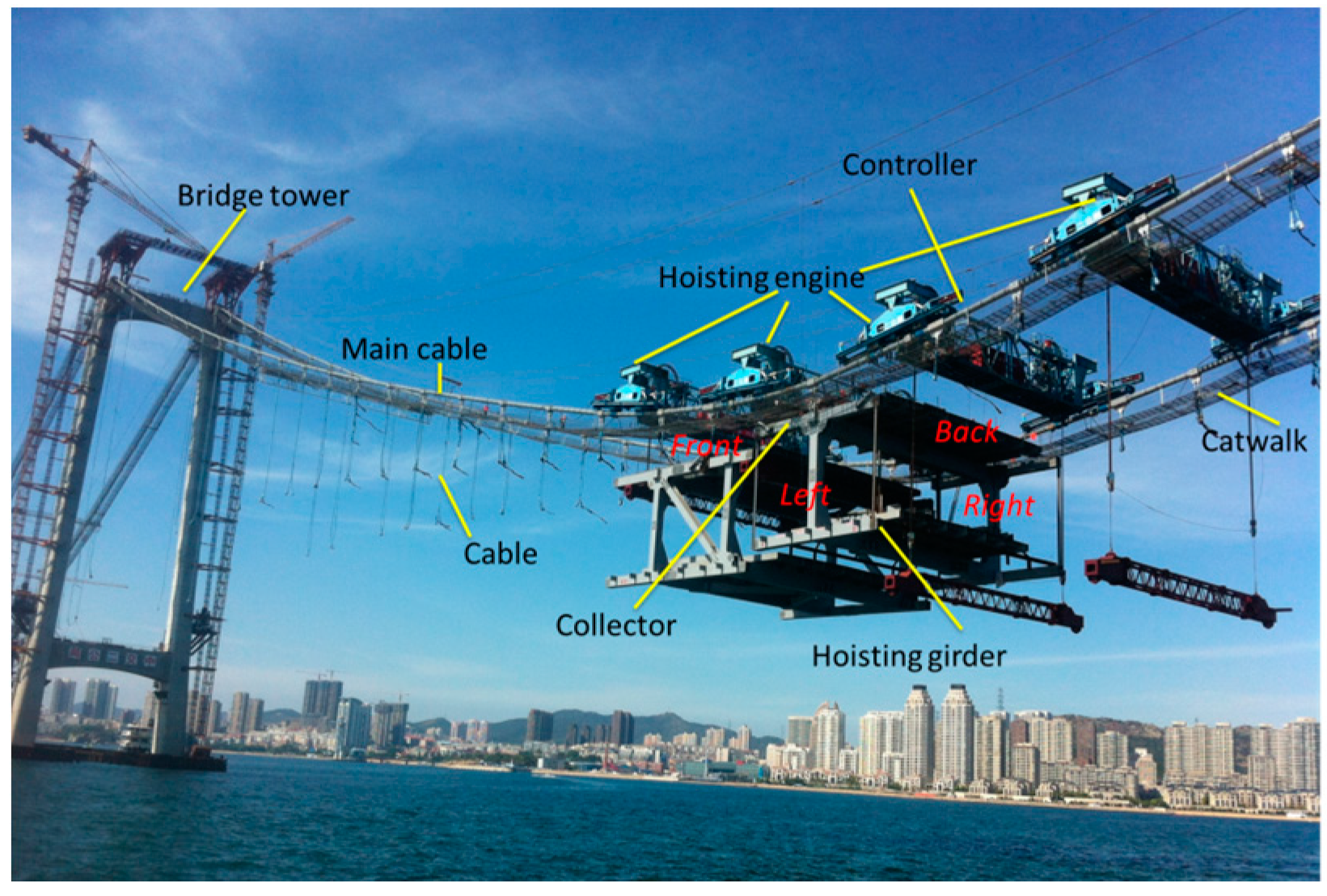
2. Engineering Description

The primary bridge is a three-span, earth-anchored suspension bridge with a double tower. Its total span is 820 m with a primary span length of 460 m and side span lengths of 180 m each. The stiffening girder is a steel truss with a height of 10 m. There are 43 girders that must be hoisted. All girders are heavy and bulky steel truss structures with weights from 264.18 to 527.19 t. Girders in the side spans must be hoisted using a floating crane, and the girders in the middle span were lifted using two cranes stretched across the two primary cables. The hoisting procedures must be implemented in good weather and calm seas, and hoisting safety is an important factor that must be considered. The monitoring for hoisting is essential to make sure the safety, and can be realized in real-time and more convenient with the developed system. The elevation of the bridge is shown as Figure 1, and the girder numbers are labeled in red. In the following parts, the girders monitored were No. 3 in side-span and No. 22 in mid-span.

3. Hoisting Monitoring System

3.1. Monitoring System Design

The monitoring system consists of a collector program that is installed on an iPhone (i.e., the collector) and a controller program that is installed in another iPhone (i.e., the controller). Additionally, a web server is used to gather the data collected by the collector iPhones and then return data to the controller.
The controller sends instructions to a collector and observes the collected data. The collector collects monitoring data through its built-in sensors after receiving instructions from the controller and returns the data to the controller every 20 s. Once the current returned data exceeds a given threshold (e.g., the threshold of acceleration is 10 m/s2, and the threshold of angle is 10°), an alarm will be triggered on the controller iPhone, which then continues collecting and monitoring. The threshold can be set on the controller at any time according to operator experience and the requirements of the on-site conditions. The flowchart of this system is presented in Figure 2.

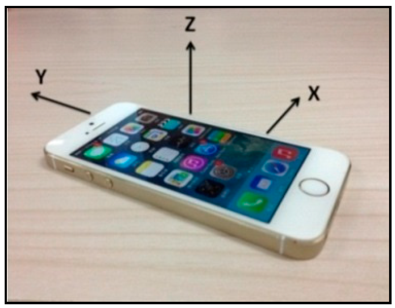
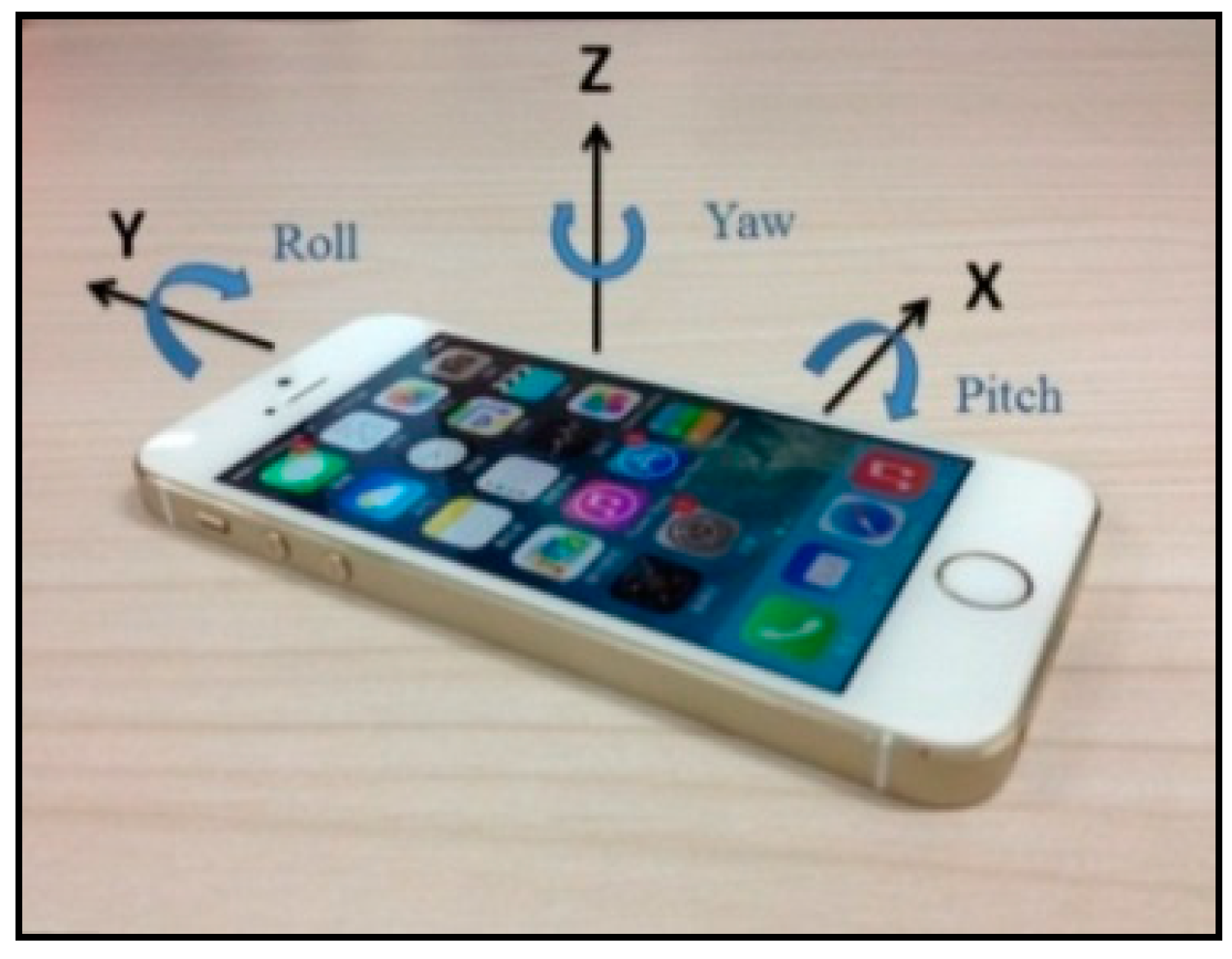
3.2. Sensor Subsystem

3.2.1. Sensor Parameters

Three parameters are primarily considered during a hoisting process: the vertical acceleration and the angles of the x- and y-axes, which will be introduced in Section 3.5. The vertical acceleration is monitored to avoid the occurrence of a sudden drop; the angles noted are examined to monitor the locations of four corners of the structure during hoisting. Acceleration is collected by the built-in BMA220-type accelerometer (Bosch, Stuttgart, Germany), which allows measurement of acceleration in three perpendicular axes. This sensor is based on micro electro mechanical systems (MEMS). Additionally, the digital resolution is 6 bit. The acceleration sensor can be programmed to optimize functionality, performance and power consumption in customer-specific applications. The angle is determined by invoking the convert function in the iPhone to read the angular rate of rotation collected by the built-in L3G4200D-type gyroscope (ST, Geneva, Switzerland), which is also a MEMS-based sensor. The gyroscope integrates low- and high-pass filters with a user-selectable bandwidth and incorporates power-down and sleep modes, a temperature sensor, and first-in first-out memory. The basic features of the accelerometer and gyroscope in the iPhone are provided in Table 1. The mechanical characteristics of the accelerometer and gyroscope in the iPhone 5S are presented in Table 2 and Table 3, respectively.
Based on the preceding characteristics, the basic performances of the accelerometer and gyroscope are stable, and these devices can thus satisfy engineering requirements in certain situations. The acceleration direction is specified as follows: regardless of the position of the phone, when the screen faces the user, the horizontal direction (i.e., left to right) is the positive direction of the x-axis, while the vertical direction (i.e., bottom to top) is the positive direction of the y-axis. The direction that faces the user is the positive direction of the z-axis, which is perpendicular to the phone’s screen. The acceleration directions are shown in Figure 3. To determine the angle, the data obtained by the gyroscope is categorized into three groups (i.e., pitch, roll, and yaw), which represent the rotation angles around the x-, y-, and z-axes, respectively. The angle-of-rotation directions are shown in Figure 4.

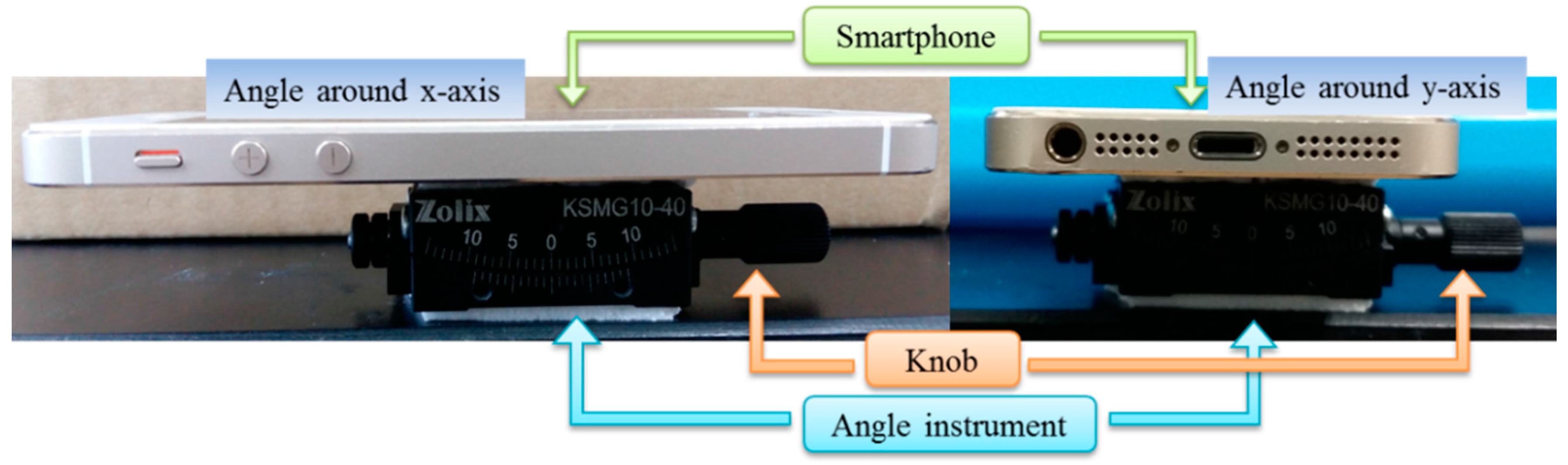
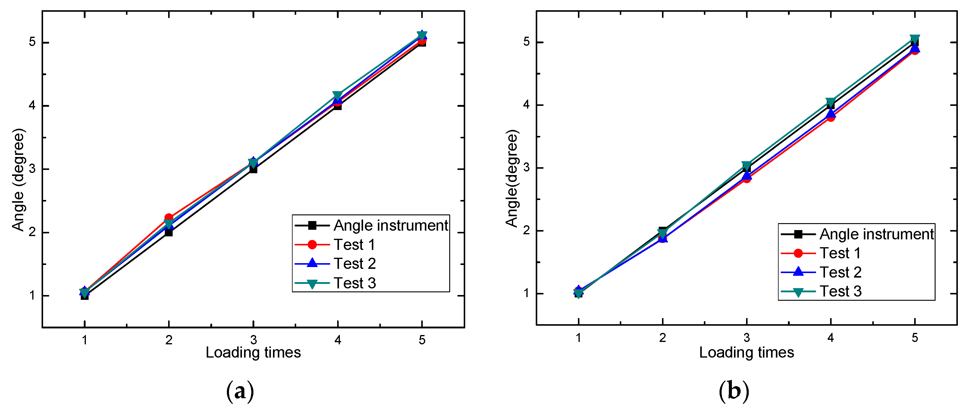
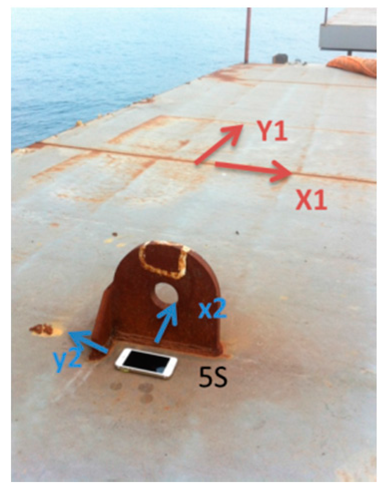
3.2.2. Calibration of Angle

In order to validate the accuracy of the angle, an angle instrument was applied to test the angle variation. The experiment photo is shown as Figure 5.
The angle instrument is fixed on the table, and the angle can be changed by turning the knob. The smartphone is fixed on the instrument, and moved with the instrument. Because of the dynamic angle data acquisition, slow manual angle loading, and low reading precise, step-by-step loading method is adopted in the experiment. Five loading steps are included in each test, one degree added every step by the angle instrument, and then keep static for several seconds, then goes to the next step. Take two experiments as examples, the angle around x-axis is shown in Figure 6a, and the angle around y-axis is shown in Figure 6b.
Several experiments were conducted, and angle steps on smart phone of three experiments are presented in Figure 7.
From Figure 7, it can be seen that the angle step coincides better with the instrument loading step. The error is inevitable because the angle on the instrument is loaded manually, and the reading is not so exact. Moreover, the loading in each experiment may be different to some extent, so the dynamic experiment was also conducted in [28]. The angle collected by the smartphone is compared to wired acquisition system and wireless sensing system, and the result proved the accuracy of angle acquisition using smartphone.

3.3. Controller Program

The controller program works with the web server to control and observe the data transmitted by the online collectors. The controller program can send instructions via the web server and make the collectors run based on these instructions. Three instructions are typically available: “start”, “stop”, and “upload data”. The “start” instruction automatically prepares the default settings and initiates the collection operation of online data collectors. The “stop” instruction controls online collectors, which are currently collecting data. The “upload data” instruction prompts online collectors to upload the data to the web server for further analysis.
Acting as the primary component of the system, the controller observes the online collectors, while the collectors collect data and returns six types of data (i.e., acceleration data of three directions and angle data of three directions) to the controller with their ID approximately every 20 s, it’s worth mentioning that the data will be returned to controller immediately once the collected data exceeds a given threshold. When the returned collected data exceeds a given threshold, the color of the corresponding monitoring parameter in the interface of the controller will change.
The web server provides data storage and push functions, which facilitate information exchange (e.g., instructions) between the controller and the collectors. The interface of the controller is shown in Figure 8, and the interface of the real-time monitoring system is shown in Figure 9.

3.4. Collector Program

The collector program uses the built-in sensors of the iPhone to collect angle and acceleration data. Prior to data collection, several variables can be set on a collector, including the collection frequency, duration, threshold, and data filename. During data collection, a collector continuously accesses its sensors to obtain data and writes their data to a file. A collector can work independently or under the control of the controller when “network control” is available. Additionally, a map position interface can be used to record the monitoring location. The interface of collector program is shown in Figure 10.

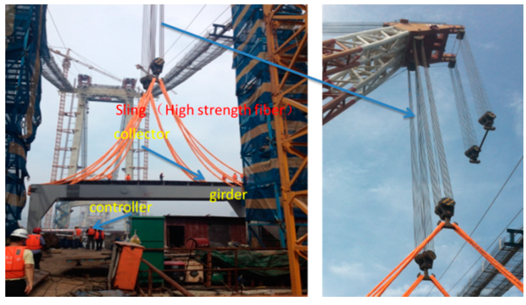
3.5. Application of the Proposed System for Monitoring a Hoisting Operation

The developed system was applied to determine the orientation of a girder during hoisting. A schematic of the hoisting process is shown in Figure 11. The collector was fixed on the girder to be hoisted, and the controller was positioned in a safe zone (i.e., a boat, on land, a catwalk, or another safe place), where operators can operate the system easily and safely. Instructions were sent from the controller to the collector via the 2G, 3G or 4G network. The collector then began to gather data upon receiving commands with a sampling frequency of 100 Hz and then returns six data at one time point (i.e., the acceleration data of three directions and the angle of three directions) to the controller every 20 s. The operator can determine the status of the hoisting procedure based on the returned data shown on the controller.
The direction of the girder is specified as follows: the x-axis runs along the span of the bridge, and the y-axis is perpendicular to the bridge. These directions within the construction site are shown in Figure 12.

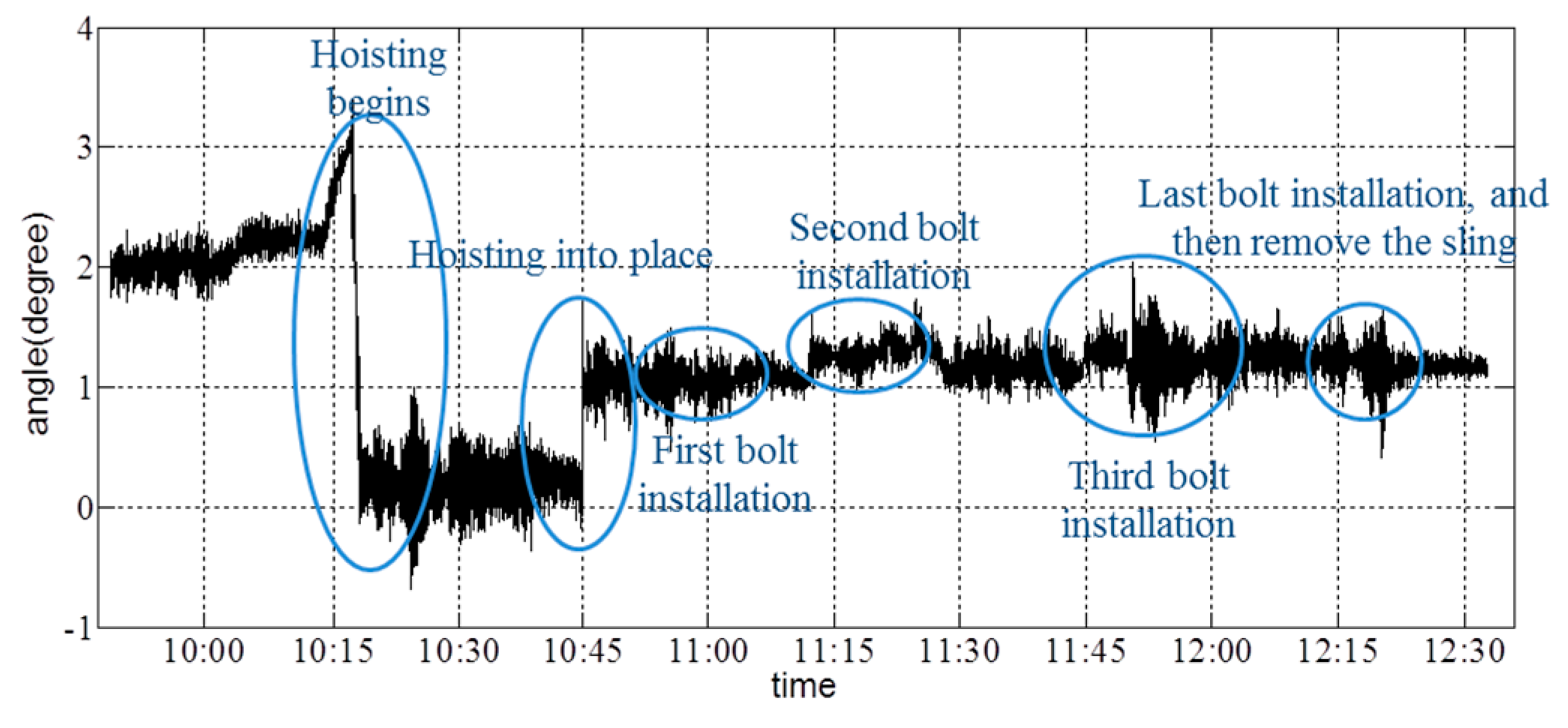
4. Monitoring of Side-Span Hoisting Procedure

4.1. Monitoring Process

The girder hoisting on one of the side spans was performed in this section. The hoisting tool used was a floating crane, and the girder, which is No. 3 in Figure 1, weighed 511.76 t. The location of the 3# girder is shown in Figure 13.
During hoisting the girder is lifted by slings that are made of a high-strength fiber. The orientation of the girder when it is suspended requires monitoring to prevent the sudden drop of one end, which would be indicated by a large angle in the front/back or right/left directions. Therefore, to obtain this real-time information and then take corresponding measures, the angle and acceleration should be monitored and relayed to the operator through the controller. During the hoisting process, an iPhone 5S gathered data as a collector, while an iPhone 4S sent instructions and received data as a controller. The on-site hoisting procedure is shown in Figure 14. The collector (i.e., the iPhone 5S) was fixed on the girder, and the controller (i.e., the iPhone 4S) was operated by a worker on a safe place. The arrangement of the phone is shown in Figure 15. The directions X1 and Y1 denote the positive directions of the x- and y-axes of the girder, and the directions X2 and Y2 represent the positive directions of the x- and y-axes of the collector. Thus, the returned data on the angle about the axis of the girder should be considered during hoisting.

4.2. Related Algorithm

In order to compare the on-site feedback and original data collected by collector, the related algorithm is shown in Figure 16. The data is collected and stored in the collector phone, and named as Angledata.txt and acceleration.txt. The data files can be exported, and then processed by MATLAB to obtain the time-history curves. In the data file, the first to the sixth column represents collected time, they are year, month, day, hour, minute and second respectively. In this test, hour, minute and second are used. In the accelerationdata.txt file, the seventh to ninth columns represent the acceleration of three axes, so the vertical acceleration is the ninth columns. In the Angledata.txt file, the seventh to ninth columns represent the angle around three axes. From Figure 15, it can be seen that, the angle around x-axis of the girder measured by smartphone is the angle around y-axis. So the eighth and seventh column is used to calculate the angle around x-axis and y-axis respectively. The original data in smartphone collected in radians, a transformational relation is used in the data processing. After the processing, the angle-history curve and acceleration history curve can be obtained to compare with the on-site feedback.

4.3. Test Results

The duration of the hoisting process was 3 h. There was no warning information on the controller during the whole procedure. At the beginning, the four corners of the girder must be hoisted simultaneously. Therefore, real-time angle information must be obtained to evaluate the position of the girder and to provide information to operators. The vertical-acceleration time-history curve of the collector is shown in Figure 17.
From the vertical-acceleration time-history curves in Figure 17, it is shown that the acceleration fluctuated to a certain extent when the girder state changed. Additionally, the maximum acceleration occurred when the girder is hoisted into its final location; the sudden touch of the girder and the column caused a major acceleration. Figure 18 and Figure 19 show the angle about the x- and y-axes of the girder.
Depending on the records of the field operator, the collector started to gather data at 9:48; the hoisting of the girder began at 10:14; the girder was lifted to a given height by 10:45; and four bolts (i.e., the connection between the cable and girder, which is shown as Figure 20) were installed completely by 12:19. The resultant deformation was severe when workers started to remove the sling. From Figure 17, Figure 18 and Figure 19, it is shown that the angle changed due to the action of hoisting in every phase of the hoisting procedure. Before each bolt was secured in its respective hole, the angle was adjusted to match up each bolt hole. Throughout the hoisting process, the acceleration and angle changed only marginally, and all disturbances remained within the acceptable ranges. Based on the preceding analysis, the girder remained stable during this hoisting operation, which is consistent with the phone investigation.

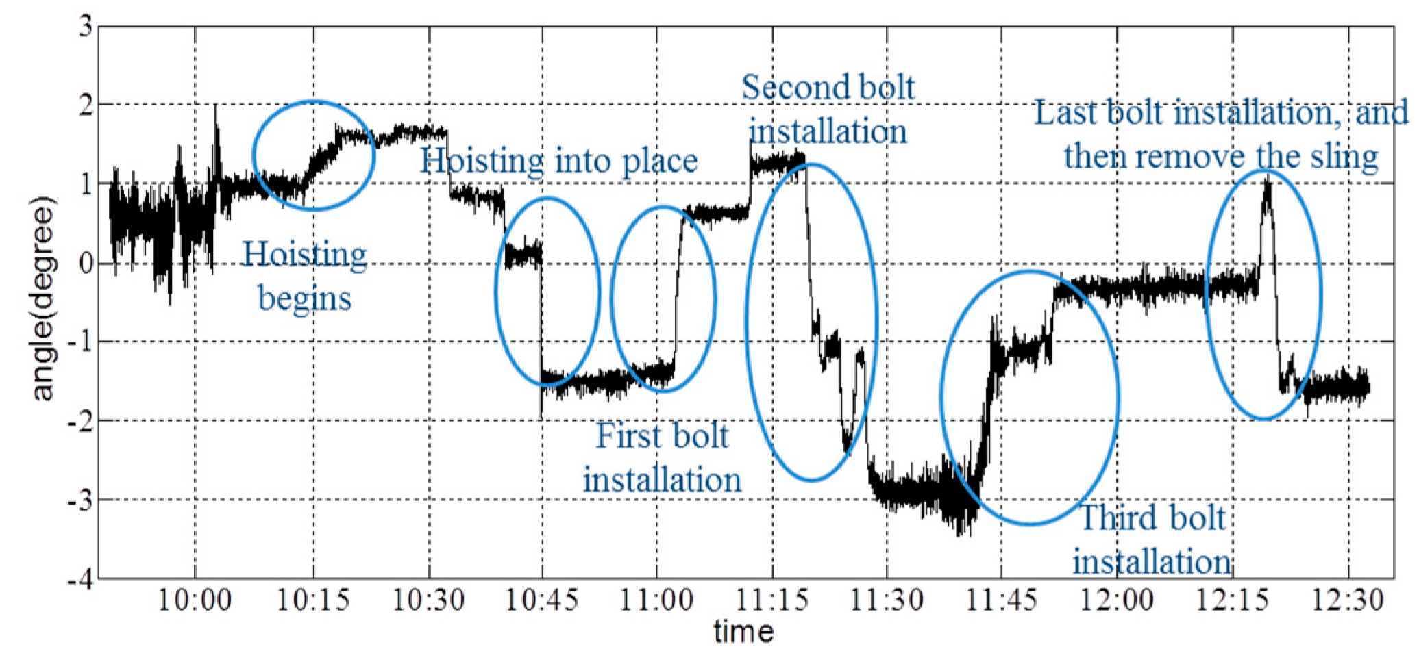
5. Monitoring of a Middle-Span Hoisting Procedure

5.1. Monitoring Process

The girder which is No. 22 in Figure 1 on the middle span weighed 372.22 t and was hoisted using two cranes. Two cranes were stretched across the two primary cables and worked together to lift the second girder into place; thus, both cranes had to raise the girder at the same rate to prevent imbalance. Therefore, the angle of the girder must be determined in real time to ensure a synchronous hoisting operation.
In this monitoring procedure, an iPhone 5S was used to collect data and return information to the controller, and an iPhone 4S served as a controller to receive the returned data and provide information to the operators. The on-site hoisting procedure is shown in Figure 21. The collector (i.e., the iPhone 5S) was fixed onto the girder to be hoisted, and the controller was operated by operators on a catwalk. The arrangement of the collector is shown in Figure 22, and Figure 23 shows the position of the collector and controller at the beginning of the hoisting operation; at this point during the hoisting procedure, the controller was on the boat. After the girder was raised from the boat, the controller was taken to a catwalk for the remainder of the hoisting procedure.
As shown in Figure 22, the collector was pointed toward a direction similar to the specified direction of the truss girder to allow operators to judge the monitored situation directly based on the feedback information received by the controller. Figure 23 shows the convenience of this method, without any other measurement devices; only two smart phones are required to obtain relevant hoisting information.

5.2. Related Algorithm

Figure 24 gives the algorithm of the middle-span hoisting monitoring. The detailed accounts are omitted because of which are similar to the algorithm in Section 4.2 except for two aspects. First is the same direction of girder and smartphone, so the seventh column is used to calculate the angle about x-axis, and the eighth column is used to calculate the angle about y-axis. Second is regarding the size and angle of the girder, the height difference in the front/back and right/left directions can only be obtained approximately. The height difference in the left/right direction can provide some information to the hoisting operators about the synchronization of the cranes on the two primary cables. The girder was 24 m long in the left/right direction and 10 m wide in the front/back direction, so the height difference can be calculated according to trigonometric function shown as Figure 24.

5.3. Test Results

The duration of the entire hoisting process was nearly 9 h—from the transmission of the “start” instruction at 9:00 to the transmission of the “stop” instruction at 17:52. The test period is so long and the battery in iPhone can function 4 h in working state, while this long field test can be achieved if an additional battery is available.
The vertical acceleration collected by the collector is shown in Figure 25 and shows that there is no significant change in the vertical acceleration of the girder. The maximum acceleration occurred at the beginning of the hoisting operation.
Figure 26 shows the angle about the girder’s x-axis; the angle about the y-axis of the girder is shown in Figure 27. Data collection began at 9:00, and the hoisting process began at 11:31. A certain angle about the x- and y-axes was generated at this time. During the initial phase of hoisting, the angle changed marginally to ensure synchronous hoisting of the two sides. Additionally, the first bolt was placed in position at 16:30. The angle about the y-axis continued to change to match the installation of the other three bolts. Based on the figures, it is shown that the acceleration and angles can be reported in real time. Lack of synchronization was not encountered during this hoisting operation.
The height difference recorded in the left/right direction is shown in Figure 28, and the height difference recorded in the front/back direction is shown in Figure 29. It is shown that the height difference in the left/right direction was adjusted to ensure the synchronization of the two cranes. At the end of hoisting process, the height on the left side was 0.7 m higher than that on the right side. The height in the front/back direction was approximately stable throughout the hoisting operation. After the first bolt was installed, the height in the front/back direction continued to increase to allow the installation of the three other bolts. After the installation of all of the pins, the height in the front of the girder was 0.75 m higher than that in the back of the girder. No alarm information appears during the on-site monitoring. Thus, the hoisting process was successful, and the last state of the girder had been prepared completely for the construction of the next day, and there is no warning information on the controller during the whole procedure.

6. Conclusions

In this study, a CPS iPhone-based system for hoisting monitoring using smartphones was proposed, including a phone collector, a controller and a server. Field monitoring results of two steel girder elements of a cross-sea bridge confirmed the convenience and practicability of this system. The dynamic acceleration and angle data of both hoisting procedures were collected and sent to a web server. The functions of sending instructions to the collectors and real-time monitoring can significantly enhance field hoisting monitoring capabilities. The changes in various angles and height differences obtained during the hoisting procedures were all within normal ranges, and there is no warning information, which indicates that the girder hoisting process was stable and safe. The real-time monitoring feedback received by the control system can provide important information to operators so that adjustments can be made during hoisting if necessary. The use of smartphone has advantages, including convenience, lower cost, the use of commonly available smartphones, and intuitive operation. Additionally, the proposed monitoring system is simple enough to be operated by any construction worker equipped with an iPhone. The rapid popularity of smart phones has provided the opportunity for researchers and civilians to understand traditional monitoring methods in a new way. For the aforementioned advantages, the use of smartphones will hopefully represent a promising trend in the CPS field.

Acknowledgments

This research was financially supported by key Projects in the National Science & Technology Pillar Program during the Twelfth Five-Year Plan Period (2011BAK02B01) and National Natural Science Foundation of China (51278085, 51479031, 51161120359), National Basic Research Program of China (2011CB013705), Program for Liaoning Excellent Talents in University (LJQ2015028), and the Fundamental Research Funds for the Central Universities (DUT15ZD117).

Author Contributions

The work presented here was carried out in collaboration between all authors. Ruicong Han, Xuefeng Zhao and Yan Yu contributed the conception and design of the monitoring system. Xuefeng Zhao and Ruicong Han carried out the field hoisting monitoring. Quanhua Guan, Weitong Hu and Mingchu Li Written the program on smartphone. Ruicong Han and Xuefeng Zhao analyzed the test data and prepared the manuscript.

Conflicts of Interest

The authors declare no conflict of interest.

References

  1. Dong, M.; Ota, K.; Yang, L.; Liu, A.; Guo, M. LSCD: A low-storage clone detection protocol for cyber-physical systems. IEEE Trans. Comput. Aided des. Integr. Circuits Syst. 2016, 35, 712–723. [Google Scholar] [CrossRef]
  2. Ganti, R.; Tsai, Y.; Abdelzaher, T. Senseworld: Towards Cyber-Physical Social Networks. In Proceedings of the IEEE Computer Society 7th International Conference on Information Processing in Sensor Networks, St. Louis, MO, USA, 22–24 April 2008; pp. 563–564.
  3. Liu, X.; Dong, M.; Ota, K.; Huang, P.; Liu, A. Service Pricing Decision in Cyber-Physical Systems: Insights from Game Theory. IEEE Trans. Serv. Comput. 2016, 9, 186–198. [Google Scholar] [CrossRef]
  4. El Baz, D. IoT and the Need for High Performance Computing. In Proceeding of the 2014 International Conference on Identification, Information and Knowledge in the Internet of Things, Beijing, China, 17–18 October 2014; pp. 1–6.
  5. Wan, J.; Yan, H.; Suo, H.; Li, F. Advances in cyber-physical systems research. KSII Trans. Int. Inf. Syst. 2011, 5, 1891–1908. [Google Scholar] [CrossRef]
  6. Wan, J.; Yan, H.; Liu, Q.; Zhou, K.; Lu, R.; Li, D. Enabling cyber-physical systems with machine-to-machine technologies. Int. J. Ad Hoc Ubiquitous Comput. 2013, 13, 187–196. [Google Scholar] [CrossRef]
  7. Wan, J.; Yan, H.; Li, D.; Zhou, K.; Zeng, L. Cyber-Physical Systems for Optimal Energy Management Scheme of Autonomous Electric Vehicle. Comput. J. 2013, 56, 947–956. [Google Scholar] [CrossRef]
  8. Wu, F.; Kao, Y.; Tseng, Y. From wireless sensor networks towards cyber physical systems. Pervasive Mob. Comput. 2011, 7, 397–413. [Google Scholar] [CrossRef]
  9. Lau, S.L.; König, I.; David, K.; Parandian, B.; Carius-Düssel, C.; Schultz, M. Supporting Patient Monitoring Using Activity Recognition with a Smartphone. In Proceedings of 2010 7th International Symposium on Wireless Communication Systems (ISWCS), New York, NY, USA, 19–22 September 2010; pp. 810–814.
  10. Wan, J.; Zhang, D.; Sun, Y.; Lin, K.; Zou, C.; Cai, H. VCMIA: A Novel Architecture for Integrating Vehicular Cyber-Physical Systems and Mobile Cloud Computing. Mob. Netw. Appl. 2014, 19, 153–160. [Google Scholar] [CrossRef]
  11. Li, W.; Lin, Y.; Ye, S. Shock Detection with smart mobile phone and its application in car accident self-rescue. Comput. Eng. 2011, 37, 245–247. [Google Scholar]
  12. Ketabdar, H.; Polzehl, T. Fall and Emergency Detection with Mobile Phones. In Proceedings of the 11th International ACM SIGACCESS Conference on Computers and Accessibility, Pittsburgh, PA, USA, 25–28 October 2009; pp. 241–242.
  13. Mladenov, M.; Mock, M. A Step Counter Service for Java-Enabled Devices Using a Built-in Accelerometer. In Proceedings of the 1st International Workshop on Context-Aware Middleware and Services: Affiliated with the 4th International Conference on Communication System Software and Middleware (COMSWARE 2009), Dublin, Ireland, 16 June 2009; pp. 1–5.
  14. Brezmes, T.; Gorricho, J.L.; Cotrina, J. Activity recognition from accelerometer data on a mobile phone. In Distributed Computing, Artificial Intelligence, Bioinformatics, Soft Computing, and Ambient Assisted Living; Springer: Berlin/Heidelberg, Germany, 2009; pp. 796–799. [Google Scholar]
  15. Lau, S.L.; David, K. Movement Recognition Using the Accelerometer in Smartphones. In Proceedings of the IEEE 2010 Future Network and Mobile Summit, Florence, Italy, 16–18 June 2010; pp. 1–9.
  16. Morgenthal, G.; Höpfner, H. The application of smartphones to measuring transient structural displacements. J. Civ. Struct. Health Monit. 2012, 2, 149–161. [Google Scholar] [CrossRef]
  17. Höpfner, H.; Morgenthal, G.; Schirmer, M.; Naujoks, M.; Halang, C. On measuring mechanical oscillations using smartphone sensors: Possibilities and limitation. In ACM SIGMOBILE Mobile Computing and Communications Review; ACM: New York, NY, USA, 2013; Volume 17, pp. 29–41. [Google Scholar]
  18. Reill, J.; Shideh, D.; Ervasti, M.; Bray, J.D.; Glaser, S.D.; Bayen, A.M. Mobile phones as seismologic sensors: Automating data extraction for the iShake system. IEEE Trans. Autom. Sci. Eng. 2013, 10, 242–251. [Google Scholar] [CrossRef]
  19. Kotsakos, D.; Sakkos, P.; Kalogeraki, V.; Gunopulos, D. Smart Monitor: Using smart devices to perform structural health monitoring. Proc. VLDB Endow. 2013, 6, 1282–1285. [Google Scholar] [CrossRef]
  20. Yi, W.J.; Gilliland, S.; Saniie, J. Wireless Sensor Network for Structural Health Monitoring Using System-on-Chip with Android Smartphone. In Proceedings of the 2013 IEEE Sensors, Baltimore, MD, USA, 3–6 November 2013; pp. 1–4.
  21. Sharma, A.; Gupta, D. Smartphone as a real-time and participatory data collection tool for civil engineers. Int. J. Mod. Comput. Sci. 2014, 2, 22–27. [Google Scholar]
  22. Oraczewski, T.; Staszewski, W.J.; Uhl, T. Nonlinear acoustics for structural health monitoring using mobile, wireless and smartphone-based transducer platform. J. Intell. Mater. Syst. Struct. 2016, 27, 786–796. [Google Scholar] [CrossRef]
  23. Feng, M.; Fukuda, Y.; Mizuta, M.; Ozer, E. Citizen sensors for SHM: Use of accelerometer data from Smartphones. Sensors 2015, 15, 2980–2998. [Google Scholar] [CrossRef] [PubMed]
  24. Ozer, E.; Feng, M.Q.; Feng, D. Citizen sensors for SHM: Towards a crowdsourcing platform. Sensors 2015, 15, 14591–14614. [Google Scholar] [CrossRef] [PubMed]
  25. Yu, Y.; Zhao, X.; Ou, J. A new idea: Mobile structural health monitoring using Smart phones. In Proceedings of the IEEE 2012 Third International Conference on Intelligent Control and Information Processing (ICICIP), Dalian, China, 15–17 July 2012; pp. 714–716.
  26. Zhao, X.; Yu, Y.; Hu, W.; Jiao, D.; Han, R.; Mao, X.; Ou, J. Cable force monitoring system of cable stayed bridges using accelerometers inside mobile smart phone. In Proceedings of the Sensors and SPIE Smart Structures Technologies for Civil, Mechanical, and Aerospace Systems, San Diego, CA, USA, 8 March 2015.
  27. Zhao, X.; Han, R.; Ding, Y.; Yu, Y.; Guan, Q.; Hu, W.; Li, M.; Ou, J. Portable and convenient cable force measurement using smartphone. J. Civ. Struct. Health Monit. 2015, 5, 481–491. [Google Scholar] [CrossRef]
  28. Yu, Y.; Han, R.; Zhao, X.; Mao, X.; Hu, W.; Jiao, D.; Li, M.; Ou, J. Initial validation of Mobile-Structural Health Monitoring method using smartphones. Int. J. Distrib. Sens. Netw. 2015, 2015. [Google Scholar] [CrossRef]
  29. Zhao, X.; Liu, H.; Yu, Y.; Zhu, Q.; Hu, W.; Li, M.; Ou, J. Convenient Displacement Monitoring Technique using Smartphone. In Proceedings of the International Conference on Vibroengineering, Nanjing, China, 26–28 September 2015; pp. 579–584.
  30. Zhao, X.; Peng, D.; Hu, W.; Guan, Q.; Yu, Y.; Li, M.; Ou, J. Quick seismic intensity map investigation and evaluation based on cloud monitoring method using smart mobile phone. In Proceedings of the SPIE Smart Structures and Materials+ Nondestructive Evaluation and Health Monitoring, International Society for Optics and Photonics, San Diego, CA, USA, 1 April 2015.
  31. Peng, D.; Zhao, X.; Zhao, Q.; Yu, Y. Smartphone based public participant emergency rescue information platform for earthquake zone—“E-Explorer”. In Proceedings of the International Conference on Vibroengineering, Nanjing, China, 26–28 September 2015; pp. 436–439.
  32. Sun, L.; Dan, D.; Sun, Z.; Yue, Q. Health monitoring system for a cross-sea bridge in Shanghai. IABSE Symp. Rep. 2006, 92, 9–16. [Google Scholar] [CrossRef]
Figure 1. Elevation of the cross-sea bridge investigated in this study.
Sensors 16 01048 g001
Figure 2. Flowchart of the monitoring and alarm systems.
Sensors 16 01048 g002
Figure 3. Acceleration directions.
Sensors 16 01048 g003
Figure 4. Angle-of-rotation directions.
Sensors 16 01048 g004
Figure 5. Photo of calibration experiment.
Sensors 16 01048 g005
Figure 6. Angle variation with step-by-step method. (a) Angle around x-axis; (b) Angle around y-axis.
Sensors 16 01048 g006
Figure 7. Angle step comparison between smart phone and angle instrument. (a) Angle step around x-axis; (b) Angle step around y-axis.
Sensors 16 01048 g007
Figure 8. Controller interface.
Sensors 16 01048 g008
Figure 9. Interface of the real-time monitoring system.
Sensors 16 01048 g009
Figure 10. Collector interface of the iPhone. (a) GPS information; (b) Gyroscope interface.
Sensors 16 01048 g010
Figure 11. Schematic of the hoisting realization process.
Sensors 16 01048 g011
Figure 12. Specified directions.
Sensors 16 01048 g012
Figure 13. Location of the second girder.
Sensors 16 01048 g013
Figure 14. On-site hoisting.
Sensors 16 01048 g014
Figure 15. Arrangement of the collector (i.e., the iPhone 5S).
Sensors 16 01048 g015
Figure 16. Algorithm of side-span hoisting.
Sensors 16 01048 g016
Figure 17. Vertical-acceleration time-history curve of the girder during hoisting.
Sensors 16 01048 g017
Figure 18. Angle about the x-axis of the girder during hoisting.
Sensors 16 01048 g018
Figure 19. Angle about the y-axis of the girder during hoisting.
Sensors 16 01048 g019
Figure 20. Bolt.
Figure 20. Bolt.
Sensors 16 01048 g020
Figure 21. On-site hoisting of the middle span.
Sensors 16 01048 g021
Figure 22. Arrangement of the collector.
Sensors 16 01048 g022
Figure 23. Position of collector and controller.
Sensors 16 01048 g023
Figure 24. Algorithm of middle-span hoisting monitoring.
Sensors 16 01048 g024
Figure 25. Vertical-acceleration time-history curve.
Sensors 16 01048 g025
Figure 26. Angle about the x-axis of the girder.
Sensors 16 01048 g026
Figure 27. Angle about the y-axis of the girder.
Sensors 16 01048 g027
Figure 28. Height difference in the left/right direction.
Sensors 16 01048 g028
Figure 29. Height difference in the front/back direction.
Sensors 16 01048 g029
Table 1. Basic features of the accelerometer and gyroscope in the iPhone.
Accelerometer (BMA220)Gyroscope (L3G4200D)
Supply voltage1.62–1.98V2.4–3.6 V
Low voltage-compatible IOS1.8 V1.8 V
Data output16 bit16 bit
Selectable full scales±2 g/±4 g/±8 g, ±16 g250 dps/500 dps/2000 dps
Output interfaceI2C/SPII2C/SPI
High shock survivabilityYesYes
Table 2. Mechanical characteristics of the accelerometer in the iPhone 5S.
ParameterConditionsTypical
Measurement range (MR)±2, ±4, ±8 g, ±16 g
Sensitivity±2.0 g16 LSB/g
±4.0 g8 LSB/g
±8.0 g4 LSB/g
±16.0 g2 LSB/g
Sensitivity change vs. temperature±2.0 g±0.01%/°C
Typical zero-g offset accuracy±2.0 g±95 mg
Operating temperature range−40 to +85 °C
Zero-g offset temperature drift−40 to +85 °C±2 mg/K
Bandwidths32, 64, 125, 250, 500, 1000 Hz
Table 3. Mechanical characteristics of the gyroscope in the iPhone 5S.
ParameterTest ConditionsTypeUnit
MR±250, ±500, ±2000dps
SensitivityMR is ±250 dps8.75mdps/digit
MR is ±500 dps17.50
MR is ±2000 dps70
Sensitivity change vs. temperature−40 °C to +85 °C±2%
Digital zero-rate levelMR is ±250 dps±10dps
MR is ±500 dps±15
MR is ±2000 dps±75
Zero-rate level change vs. temperatureMR is ±250 dps±0.03dps/°C
MR is ±2000 dps±0.04
Digital output data rate100, 200, 400, 800Hz

