Mechanical Booster Pump-Assisted Thermochemical Mode for Low-Grade Heat Storage and Upgrading: A Thermodynamic Study
 Tao Zeng1,2,3
  Jun Li1,2,3*
  Lisheng Deng1,2,3 Zhaohong He1,2,3
  Noriyuki Kobayashi4 Rongjun Wu4
  Hongyu Huang1,2,3*
- 1Guangzhou Institute of Energy Conversion, Chinese Academy of Sciences, Guangzhou, China
- 2Key Laboratory of Renewable Energy, Chinese Academy of Sciences, Guangzhou, China
- 3Southern Marine Science and Engineering Guangdong Laboratory (Guangzhou), Guangzhou, China
- 4Department of Chemical Systems Engineering, Nagoya University, Nagoya, Japan
To assure stable and dependable functioning of the thermochemical energy storage (TCES) system under unstable low-grade heat temperatures, three mechanical booster pump-assisted TCES (MBP-assisted TCES) modes operating with SrBr2·H2O/H2O, LiOH/H2O, and CaCl2·H2O/H2O are proposed for the application of heat storage and upgrading. The operating modes are the MBP-assisted charging mode (A mode), MBP-assisted discharging mode (B mode), and MBP-assisted charging and discharging mode (C mode). A thermodynamic model is established to evaluate the influences of condensing temperature, compression ratio, MBP isentropic efficiency, and reaction advancement on the heat source temperature and system performance from both energy and exergy perspectives. The results indicate that compared with the other two modes, the B mode is more effective in reducing the heat source temperature and achieving better system performance. Compared to the conventional TCES mode, the proposed modes can operate at lower heat source temperatures that can be minimized by up to 21∼25°C by employing the B mode with a compression ratio of 3.0 at the condensing temperature of 24°C. The B mode with SrBr2·H2O/H2O exhibits the highest energy and exergy efficiencies that the coefficients of performance based on total energy input and electric power consumed (COPtotal and COPelec), and exergy efficiency varies in the range of 0.53∼0.59, 7.4∼19.6, and 0.78∼0.95, respectively. In contrast, CaCl2·H2O/H2O shows the lowest system performance, but a higher heat output temperature can be required. In addition, to maintain the MBP discharge temperature below 180°C, there is a maximum permitted compression ratio that varies depending on the operating modes, operating conditions, and working pairs. The findings of this research can be used as theoretical references and suggestions for selecting MBP-assisted TCES modes, operating conditions, and working pairs for low-grade heat storage and upgrading.
1 Introduction
The COVID-19 pandemic has had a dramatic impact not only on the human health and environment but also on the global energy industries and markets in unprecedented ways. According to the International Energy Agency, global coal demand and electricity consumption are estimated to have declined by 5.2% and 1.5%, respectively, in 2020 (International Energy Agency (IEA), 2020a). Despite reductions in greenhouse gas (GHG) emissions and improvements in air quality during the pandemic, it is estimated that COVID-19’s influences on climate change remain uncertain but are almost negligible (Forster et al., 2020). Based on the hypothesis of the economic recovery from the crisis in 2021, the global coal demand is anticipated to recover, increasing by 2.6%, 7,432 Mt (International Energy Agency (IEA), 2020a). GHG emissions are strongly related to global coal consumption, which is the greatest source of energy-related CO2 emissions (International Energy Agency (IEA), 2020b). In China, the world’s largest energy consumer and GHG emitter, it is reported that the industrial sector accounts for about 70% of the total energy consumption, among which more than 50% is directly discharged into the environment, and almost 60% of that can be potentially recovered (Lu, 2019).
To put the world on a trajectory toward accomplishing the Paris Agreement’s goal of avoiding the increase in global average temperature to 2°C and ideally 1.5°C above pre-industrial levels (United Nations Framework Convention on Climate Change, 2015), emissions must decrease at an average rate of 7% per year (Ivanova, 2020), indicating much more effective and rapid cuts in GHG emissions are required. In addition, the COVID-19 crisis has highlighted the importance of developing a cleaner, more flexible, and sustainable energy supply system. Industrial waste heat and renewable energy such as solar, thermal, and geothermal energy are considered promising energy sources for supplying hot water for domestic and industrial purposes, owing to their enormous amounts and environment-friendly nature. However, the instability and spatiotemporal dependence of these heat sources hinder their efficient and broader utilization.
Thermal energy storage (TES) is acknowledged as one of the promising energy-efficient technologies to alleviate the instability of heat sources and bridge the spatiotemporal gap between energy supply and demand and, therefore, reduce GHG emissions. TES can be categorized as sensible heat storage, latent heat storage, and thermochemical energy storage (TCES). Compared with the first two storage systems, TCES exhibits high energy storage density, long-term storage with negligible heat loss, and feasibility of releasing heat at the desired temperature within a specific range. However, TCES is still in the laboratory stage and has not been applied commercially. The current strategy for improving TCES mainly focuses on the development of high-performance materials (Courbon et al., 2017a), advanced reactor design (Hawwash et al., 2020; Zeng et al., 2021), and system optimization (Johannes et al., 2015; Jiang et al., 2017). In addition, some innovative cycle configurations are introduced to enhance the performance of TCES under unstable operating conditions driven by low-grade thermal energy such as solar energy or industrial waste heat.
As early as 1883, the idea of combining the absorption/desorption process with a mechanical expander/compressor had been proposed by Moritz Honigmann (Fitó et al., 2019). To improve the cooling coefficient of performance (COP) (usually less than 1) of the heat-driven metal hydride heat pump system, Park et al. (2002) experimentally evaluated the operating characteristics of a compressor-driven metal hydride heat pump (CDMHHP) system. A suitable metal hydride was chosen for the given oil-type compressor. Results indicated that, under the optimum operating conditions, the maximum cooling power and COP of the system were 353 kcal/kg-alloy h and 1.8, respectively. In order to solve the limitations caused by the low efficiency of the small mechanical compressor and the oil contamination of metal hydride, Tao et al. (2015) proposed a new CDMHHP system using an electrochemical compressor and developed a thermodynamic model to predict the system performance. Results showed that the electrochemical compressor-driven system is more suitable for a cooling capacity of less than 200 W and could potentially achieve a higher COP than the existing system.
Bao et al. (2016) investigated an integrated chemisorption system composed of reactors, compressors, and expanders to recover low-grade heat under 100°C for simultaneous electrical power and thermal energy storage. System performances in terms of energy efficiency, exergy efficiency, and energy density for three types of NH3–metallic salts pairs were theoretically studied. The proposed system could recover the low-grade thermal energy effectively and has broader application with higher penetration of renewable energy compared with conventional systems. Van der Pal et al. (2011) explored a hybrid adsorption–compression heat pump based on LiCl–MgCl2–NH3 reactions to improve the flexibility toward unstable operating temperatures of the ordinary TES system. It was demonstrated that the hybrid system was capable of expanding the lower limit of driving temperature and increasing the upper limit of output temperature while attaining acceptable power densities and COP values, despite its annual savings being about 30% less than that of the ordinary TES system. Furthermore, Van der Pal et al. (2013) experimentally and theoretically investigated a hybrid heat pump system that combined a silica gel–water adsorption system with a roots-type compressor. In contrast with a purely heat-driven system, the hybrid system can produce noticeably higher chilling power and thermal efficiency. In addition, results indicated that the compressor placed between the evaporator and the reactor showed better system performance than the compressor located between the condenser and the reactor. Ferrucci et al. (2018) devoted their efforts to developing a mechanical compressor-driven thermochemical storage system using BaCl2 as the reactant salt and NH3 as the working fluid/refrigerant. The proposed system combined a thermochemical reactor with a conventional mechanical vapor compression cycle driven by photovoltaic energy. The COP, exergy efficiency, and cooling capacity were evaluated theoretically. Results demonstrated that a 20°C reduction of reacting temperature was acquired compared with the 100% solar-thermal-driven thermochemical system. In addition, when utilizing a heat source temperature of 50°C, the system could supply a cooling capacity of 4 kWh/day/m2 solar collector, which is superior to that of other systems analyzed.
To make the salt/NH3 heat pump continuously and efficiently upgrade the low-grade industrial waste heat, Gao et al. (2019) proposed a novel pressure boost thermochemical sorption heat pump (PBTSHP) using only one sorbent. The performance comparison between the proposed system and conventional vapor compression heat pump (CVCHP) system was conducted by a thermodynamic model. It turned out that the COP of the PBTSHP system applying SrCl2/NH3 as the reactant pair was 6.5, which was prominently higher than that of the CVCHP under identical operating conditions. Then, they designed a hybrid cascade heat pump system that coupled the PBTSHP with the CVCHP to achieve higher temperature lift. However, this system could not utilize the waste heat continuously because only one thermochemical reactor was installed in the cycle. To make the solid sorption–compression refrigeration system operate efficiently and continuously at a lower waste heat temperature and tackle the issue that it is difficult to recover waste heat with temperature lower than 90°C using the conventional solid sorption refrigeration system, Gao et al. (2021) fixed a compressor between the thermochemical reactor and the condenser to regulate desorption pressure. Performance analysis was carried out theoretically, and it was concluded that the hybrid system’s COP was practically independent of the evaporating temperature at a given heat source temperature due to the stable pressure ratio and power consumption of the compressor. Furthermore, the hybrid system could be driven efficiently by the heat source temperature of 60–90°C by adjusting the compressor’s suction pressure.
In summary, previous research has demonstrated that hybrid systems exhibit the advantages of broadening the operating temperature window, enhancing the heat output performance, and improving the system’s energy efficiency. However, the research studies mentioned above mainly focus on cooling and refrigeration applications using NH3 as a working fluid. Water is considered one of the most desirable working fluids for TCES systems due to its safety, easy availability, and environment-friendly nature. To the authors’ knowledge, few works have been dedicated to such a hybrid system employing water as a working fluid for space heating and domestic hot water applications. Numerous thermochemical storage materials have been investigated (Liu et al., 2021). Among them, strontium bromide (SrBr2) (Zhang et al., 2016; Cammarata et al., 2018), calcium chloride (CaCl2) (Courbon et al., 2017b; Jabbari-Hichri et al., 2017), and lithium hydroxide (LiOH) (Li et al., 2020; Li et al., 2021) possess high energy storage density, safe performance, and favorable reaction temperature that exhibit great potential for a low-temperature water-based TCES system. As a result, they were targeted in this study.
To guarantee the stable and reliable operation of the TCES system under low-grade driving temperature, this study proposes a mechanical booster pump-assisted thermochemical energy storage system (MBP-assisted TCES system) implementing SrBr2·H2O/H2O, LiOH/H2O, and CaCl2·H2O/H2O as working pairs. The effects of condensing temperature, compression ratio, MBP isentropic efficiency, and reaction advancement on the heat source temperature and system’s energy and exergy efficiencies are theoretically investigated and discussed in detail. This study can offer theoretical references for the design and development of TCES systems driven by fluctuating low-grade thermal energy.
2 Methodology
2.1 Principle of the MBP-TCES System
The reversible reactant salt–water vapor thermochemical reaction is generally expressed as follows:
where M·(x + y)H2O is the reactant salt rich in water, M·yH2O is the reactant salt poor in water, ΔHr is the enthalpy of the reaction per mole of water, and x is the stoichiometric coefficient.
Figure 1 illustrates the P–T diagrams of the proposed and conventional modes by employing the SrBr2·H2O/H2O pair, which is applied for a detailed description of the operating principle. During the charging (also known as dehydration) process of the conventional system, the reactant salt M·(x + y)H2O packed in the reactor absorbs heat from low-grade thermal energy (at T1′) and decomposes into its less-hydrous or anhydrous form M·yH2O and water vapor at condensation pressure (Pcon); meanwhile, the thermal energy is steadily stored in the bonds of chemical compounds. This procedure is an isobaric step, corresponding to the ①′→② process in Figure 1. The water vapor flows out of the reactor into the condenser and condenses into a liquid by transferring heat to the environment at T2, as follows:
where ΔHeva corresponds to the evaporation enthalpy of water.
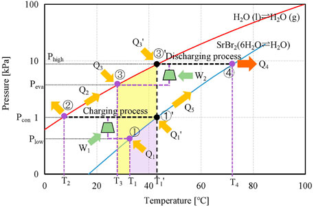
FIGURE 1. P–T diagrams of the proposed and conventional TCES modes with SrBr2·H2O/H2O.
For the proposed system, the MBP is located between the reactor and the condenser. With the aid of the MBP, the charging process is conducted at a lower pressure (Plow) than Pcon, meaning it can operate at a lower temperature level (T1) compared to the conventional system (T1′), as shown in Figure 1. The desorbed water vapor is pressurized to Pcon by the MBP and condensed at ambient temperature (T2), corresponding to a non-isobaric step of ①→②. Consequently, the proposed system can effectively reduce the requirement of charging temperature (region shown in purple and denoted as ΔT1 = T1′−T1), facilitating the utilization of low-grade thermal energy.
After the charging process, the reactors of the conventional and proposed systems follow the preheating process of ①′→④ and ①→④, respectively, by utilizing a portion of the hydration heat of Eq. 1 or the superheated water vapor produced by the MBP in the proposed system. Meanwhile, the condensers of the conventional and proposed systems are heated from T2 to the evaporating temperature of T1′ and T3, ②→③′ and ②→③, respectively, when the charging and discharging processes operate discontinuously; e.g., the solar thermal energy is stored during daytime while released at night.
During the discharging (hydration) process of the conventional system, a low-grade thermal energy is used to provide the required heat (Q3) for vapor generation, corresponding to the left-to-right process in Eq. 2 and displayed as ③′→④ in Figure 1. The water vapor from the evaporator at the saturation pressure of Phigh corresponding to the low-grade heat temperature (T1′) flows toward the reactor, where it reacts with M·yH2O inside the reactor and releases the reaction heat in a higher temperature level (T4). For the discharging process in the proposed system, the MBP is located between the evaporator and the reactor. The water vapor pressure is boosted from Peva to Phigh by the MBP when the heat source temperature (T3) is inferior to the required operating temperature (T1′). Hence, the evaporation can take place at a lower vapor pressure (Peva) leading to a lower driving temperature (T3) while maintaining the same discharging temperature (T4) as the conventional one. The reduction in driving temperature is denoted as ΔT2 = T1′ − T3 (region shown in yellow).
The operation principle mentioned above demonstrates that both the MBP-assisted charging and discharging processes of the TCES system can enlarge the operating temperature range.
In this study, three types of MBP-assisted modes according to the installation position of MBP are evaluated, i.e., the MBP-assisted charging mode (A mode, Figure 2A), MBP-assisted discharging mode (B mode, Figure 2B), and MBP-assisted charging and discharging mode (C mode, Figure 2C). In order to facilitate comparison, the conventional mode is also depicted in Figure 2D.
(1) For the A mode, the MBP is located between the reactor and the condenser in the charging process. The discharging process runs identically as in the conventional one. This mode is characterized by four temperature levels (T2 < T1 < T1′ < T4) and three pressure levels (Plow < Pcon < Phigh).
(2) For the B mode, the MBP is located between the evaporator and the reactor in the discharging process. The charging process runs in the same manner as in the conventional one. This mode is characterized by four temperature levels (T2 < T3 < T1′ < T4) and three pressure levels (Pcon < Peva < Phigh).
(3) For the C mode, two MBPs are individually installed in charging and discharging processes. This mode is characterized by four temperature levels (T2 < T1 < T3< T4 or T2 < T3 < T1 < T4, depending on the compression ratio) and four pressure levels (Plow < Pcon < Peva < Phigh).
(4) For the conventional mode, no MBP is installed and is characterized by three temperature levels (T2 < T1′ < T4) and two pressure levels (Pcon < Phigh).
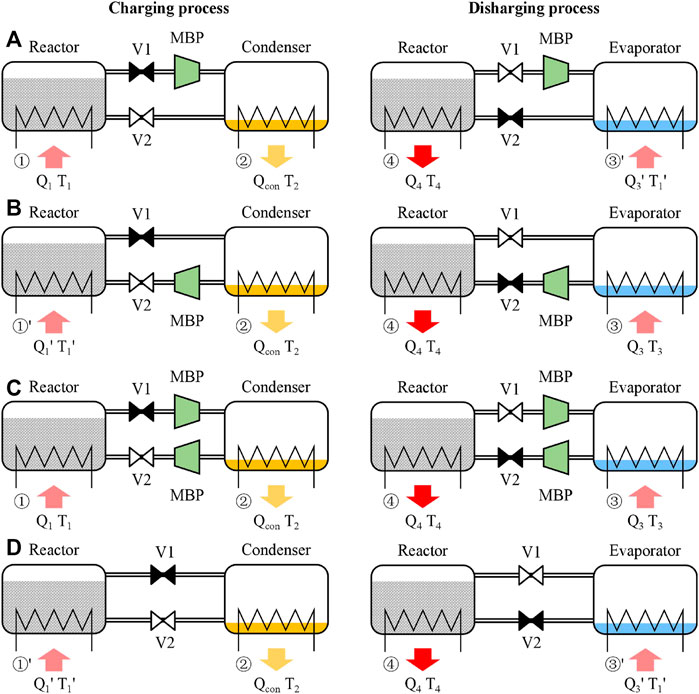
FIGURE 2. Schematic diagram of the (A) MBP-assisted charging mode, (B) MBP-assisted discharging mode, (C) MBP-assisted charging and discharging mode, and (D) conventional TCES mode (symbols ⧓ and ⋈ indicate the valve is opened and closed, respectively).
It is worth noting that T1 and T3 can be either the same or different, depending on the heat source temperature and the compression ratio of the MBP. The switch of the charging and discharging process can be realized by regulating Valve 1 (V1) and Valve 2 (V2); i.e., V1 is open, and V2 is closed in the charging process, while operating reversely in the discharging process. Table 1 describes the operating points depicted on the P–T diagrams and schematic diagrams for charging and discharging processes in the proposed and conventional modes.
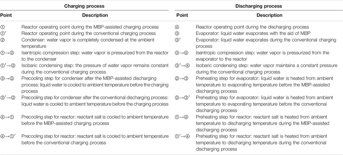
TABLE 1. Explanation of the operating points illustrated on the P–T chart and schematic diagram for the proposed and conventional modes, corresponding to Figures 1, 2.
2.2 Model Assumptions
The following assumptions have been made:
(1) The system works under steady-state conditions
(2) For each reactor, the mass of the reactant salt (SrBr2·H2O, LiOH/H2O, and CaCl2·H2O) is assumed to be 2 kg
(3) Except for heat sources and sinks, heat exchange with the surrounding environment is neglected for all components
(4) The temperature difference between the outlet and inlet heat transfer medium in the components (i.e., reactors, evaporator, and condenser) is 0°C
(5) For exergy calculation, the reference temperature equals to the ambient temperature
(6) The influence of the component’s heat capacity is not taken into account
(7) Pressure drop through the pipelines, valves, and reactive salts is negligible
(8) Thermal properties of the reactive salt and heat transfer medium are constant during the cycle
(9) The deviation from the P–T equilibrium lines and the hysteresis between hydration and dehydration are negligible
2.3 Thermodynamic Model
The reversible chemical reaction of the three selected salts with water vapor can be formulated as follows:
The liquid–vapor equilibrium line of water and solid–vapor equilibrium line of the thermoplastic material are determined by the Clausius–Clapeyron relation (Goetz et al., 1993), as follows:
where P0 is the reference pressure (100 kPa); P and T are the equilibrium pressure and temperature of the liquid–vapor or solid–vapor, respectively; R is the ideal gas molar constant [J/(molK)]; and ΔHr and ΔSr are, respectively, the standard enthalpy of reaction [J/mol] and standard entropy of reaction [J/(mol K)] per mole of water vapor and hypothesized to not change with temperature. The thermodynamic parameters of the water and reactant salts are tabulated in Table 2, while the P–T curves of pure water and selected reactant salts are illustrated in Figure 3.
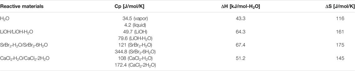
TABLE 2. Thermodynamic parameters for reactive materials (Lide, 1999; Engineering ToolBox, 2004; Lahmidi et al., 2006; Glasser, 2014; Kubota et al., 2014; Abernathy and Brown, 2015; Fopah-Lele and Tamba, 2017; Cal-Chlor Corporation, 2018; Livent, 2018).
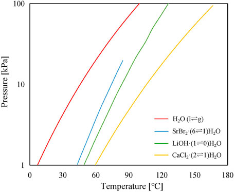
FIGURE 3. Thermodynamic equilibrium of water and the selected thermochemical working pairs of SrBr2·6H2O, LiOH·H2O, and CaCl2·2H2O.
The outlet vapor from the MBP is required to be heated up to the output temperature of the reactor (T4) and is calculated as follows:
where cp,v is the specific heat of water vapor at MBP discharge; Td is the temperature of vapor exiting the MBP; ΔNH2O is the theoretical molar amount of water vapor which is released from M·(x + y)H2O during the charging process or adsorbed by M·yH2O within the discharging period; and ηr is reaction advancement representing the fraction of actual molar amount of released or adsorbed water vapor at any moment during the process relative to the theoretical molar amount of water vapor, which is employed to indicate the degree of completeness of the reaction. It is worth mentioning that the increasing Td reduces the heat load requirement. When Td > T4, the surplus heat contained in water vapor is conducive to the heat output of the reactor.
The heat load required for the reactant salts to reach the operating conditions of the discharging process, i.e., T4 and Phigh, can be calculated as follows:
where cp,MxH2O and cp,M·(x+y)H2O are, respectively, the specific heat of M·(x + y)H2O and M·xH2O; vH2O is the stoichiometric coefficient of H2O in Eq. 1.
In the preheating process, a part of the hydration heat, which is given by Eq. 9, is employed to heat up the reactant salt.
The output heat of the reactor can then be obtained by subtracting Qv and Qsalt from Qr, as follows:
The actual power consumed by the MBP per mole of vapor in [kJ/mol] can be obtained by employing the following equation:
where T and P represent the temperature and pressure of water vapor, respectively; subscripts s and d denote the suction and discharge port of the MBP, respectively; and isentropic efficiency, ηp, is defined as a ratio of power consumed by the MBP under isentropic conditions to the actual power consumed. Depending on design and size, typical compressor isentropic efficiency ranges from 65% to 100% (Cengel and Boles, 2015). The isentropic efficiency range of 70%∼90% has been considered in this study. R is the ideal gas constant [J/mol/K]. k is the ratio of specific heat at constant pressure (cp,v) to specific heat at constant volume (cv,v) [1.33 for water vapor (Engineering ToolBox, 2003)], expressed as follows:
Compression ratio is defined as the ratio of the MBP’s discharge pressure (Pd) to suction pressure (Ps) and can be calculated as follows:
In the case of the MBP-assisted charging mode, Ps is the reactor pressure at heat source temperature and Pd is equal to the condensing pressure at ambient temperature, while in the case of the MBP-assisted discharging mode, Ps is the same as the evaporating pressure at heat source temperature and Pd is the reactor pressure that corresponds to the output temperature of the reactor.
The discharge temperature of the MBP is given by
Similarly, the heat required to heat up the reactant salt from ambient temperature to the charging temperature in the charging process is given by the following equation:
Consequently, the total heat supplied to the reactor during the charging process can be obtained by summing up Q0 and the dehydration reaction heat which is assumed to be identical to the hydration heat as Eq. 9.
In the preheating process ②→③, the heat needed to raise the liquid water in the condenser from ambient temperature to the evaporating temperature is expressed as follows:
In the evaporating process, the heat supplied to the evaporator can be written as follows:
where ΔHr is the enthalpy of vaporization of water at T3.
In the precooling step, the heat exchange between the reactor/condenser and the environment is not considered in evaluating the performance indicators because the environment plays the role of a heat sink. Consequently, this topic will not be discussed further here.
2.4 Performance Indicators
In order to quantify the enhancements achieved by the MBP-assisted TCES modes over the conventional system, several key performance indicators have been considered as follows.
Two distinct coefficients of performance, i.e., the total coefficient of performance (COPtotal) and the electrical coefficient of performance (COPelec), are defined to investigate system performance from the first law of thermodynamics perspective. COPtotal is the ratio of the useful heat output from the reactor during the discharging process to the total energy consumption of the system, illustrated as follows:
where Wp,t is the total power consumption of the MBP in the charging and discharging process, in [kJ].
COPelec is the ratio of the useful heat output from the reactor during the discharging process to the power consumed by the MBP. It can be used to compare with the heat pump system and is represented as follows:
The investigation based on the first law does not account for the energy quality. In order to obtain a more comprehensive thermodynamical performance assessment for the proposed system, the exergy analysis that relies on the second law of thermodynamics has also been studied. Exergy analysis provides an accurate indication of the available exergy that can be utilized from a system when it reaches the thermodynamic equilibrium with the reference environment. Exergy efficiency is a ratio of output flow of exergy to input flow of exergy, defined as follows:
where the output exergy corresponds to exergy of the heat discharged from the reactor at T4 to the environment; the input exergy is the sum of the exergies associated with heat transfer from T2 to T1 in the reactant salt during the charging process, the heat required to warm up the liquid water from T2 to T3, the vaporization heat required for the evaporation, and the work input to the MBP. The first and second terms in the denominator are defined as the input exergy caused by heat transfer, while the last term represents the input exergy induced by the electric power consumed.
3 Results and Discussion
Thermodynamic analysis from the perspective of energy and exergy is conducted to investigate the influence of selected critical operating parameters (MBP isentropic efficiency, compression ratio, reaction advancement, and condensing temperature) on system performance. Compression ratios generally vary between 1.05∼10 according to the type of compressor (Kayode Coker, 2015). Due to the simple structure, good stability, small vibration, and no lubricant contaminations, the roots water vapor compressor is widely used in various industrial processes for compression of vapor stream with a commonly used compression ratio range of 1.2∼2.4 (Hong et al., 2018; Hu et al., 2018). In this research, the maximum compression ratio of MBP is set as 3. Regarding the discharge temperature of the compressor, it is recommended by manufacturers that it should not exceed 180°C to prevent oil degradation, which may cause deterioration in the compressor’s performance and lead to subsequent reduction of their service life (Ferrucci et al., 2018). In addition, condensing temperatures are selected based on the average autumn and winter temperature range in the Cantonese region of Southern China.
3.1 Comparison of Heat Source Temperature and MBP Discharge Temperature
Figure 4 illustrates the heat source temperature as a function of the compression ratio at different condensing temperatures. Solid lines and dotted lines indicate the discharging process and charging process, respectively. Cr = 1.0 represents the conventional mode without the MBP, while Cr > 1.0 indicates the proposed modes with the MBP. During the simulation, the heat output temperatures of the reactor in the discharging process at the condensing temperature of 7, 16, and 24°C are set as 72, 78, and 83°C for SrBr2·H2O/H2O; 87, 94, and 100°C for LiOH/H2O; and 122, 135, and 146°C for CaCl2·H2O/H2O, respectively. According to Figure 4, the heat source temperature is lower for a higher compression ratio. This is because the discharge pressure of the MBP set at a fixed value results in the decrease in suction pressure with the increased compression ratio, and therefore, lower heat source temperature is required. Taking the CaCl2·H2O/H2O working pair as an instance (Figure 4C), the discharging process can work when the driving temperature is higher than 38°C under Cr = 3.0 and Tcon = 24°C; however, the lowest driving temperature is about 60°C for the conventional mode (i.e., Cr = 1.0). As the condensing temperature decreases, the heat source temperature reduces due to the lower condensing temperature corresponding to lower vapor pressure, as can be predicted from Figure 1. In addition, it can be observed that heat source temperatures required for the charging process are higher than those of the discharging process under the same operating conditions. This is mainly because the condenser pressure in the charging process is much lower than that of the reactor in the discharging process, leading to a smaller change in pressure during the charging process under the same compression ratio and, thus, a smaller temperature change. It should be mentioned again that heat source temperatures in both processes are equal at the compression ratio of 1 (i.e., the conventional thermochemical cycle), thus giving rise to the abovementioned results.
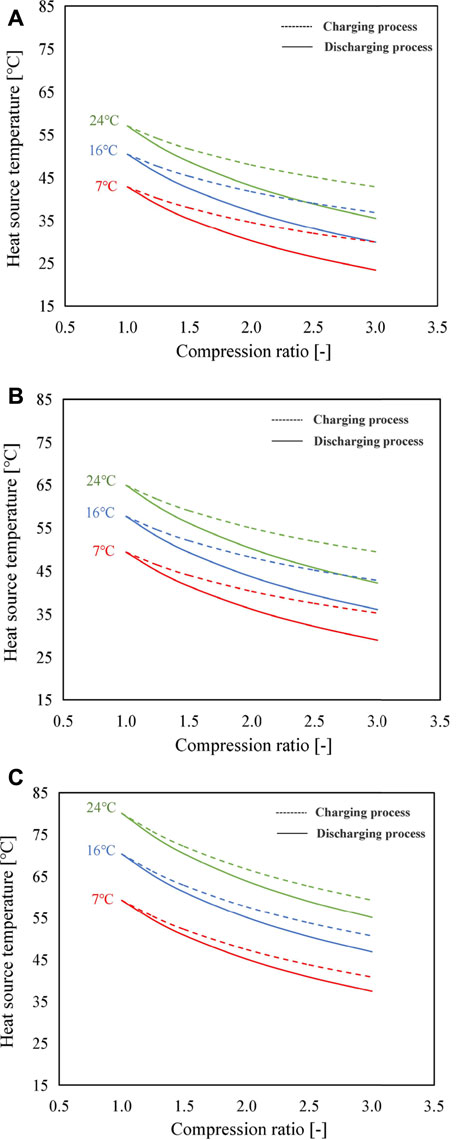
FIGURE 4. Variation of heat source temperature with the compression ratio by using (A) SrBr2·H2O/H2O, (B) LiOH/H2O, and (C) CaCl2·H2O/H2O as the working pair for three scenarios of condensing temperature (solid lines: discharging process; dotted lines: charging process).
Using the proposed modes, the heat source temperature can be adjusted in a wider range when necessary. For example, in the case of SrBr2·H2O/H2O, when the compression ratio increases from 1.0 to 3.0, heat source temperatures of the evaporator (discharging process) and reactor (charging process) decrease from 57°C to 36°C and 43°C at the condensing temperature of 24°C, from 50°C to 30°C and 37°C at the condensing temperature of 16°C, and from 43°C to 23°C and 30°C at the condensing temperature of 7°C, respectively.
Figure 5 shows the variation of MBP discharge temperature for different condensing temperatures at different compression ratios. As can be seen from Figure 5, the discharge temperature of the MBP has a rising trend with the increase of compression ratio that shows the opposite tendency to that of the heat source temperature. Additionally, it can be noticed that the improvement of MBP isentropic efficiency is associated with a reduction in the MBP discharge temperature, and the magnitude of this reduction becomes more obvious with an increase in compression ratio. For example, when using SrBr2·H2O/H2O, the temperature reduction achieved between the isentropic efficiency of 70% and 90% at the condensing temperature of 24°C rises from 11°C to 31°C as the compression ratio increases from 1.5 to 3.0. This is attributed to MBP discharge temperature that is proportional to the compression ratio but inversely correlated with MBP isentropic efficiency for a given heat source temperature, according to Eq. 11. The discharge temperature of the MBP in the charging process is higher than that of the discharging process caused by the higher Ts, as revealed in Figure 5. In addition, due to the higher heat source temperature requirement, CaCl2·H2O/H2O has a greater MBP discharge temperature than the other two pairs. The highest MBP discharge temperature is noticed under the operating conditions of Tcon = 24°C, Cr = 3.0, and ηp = 70% in the charging process, which is 207°C for CaCl2·H2O/H2O, followed by 193°C for LiOH/H2O and 184°C for SrBr2·H2O/H2O. To ensure that the discharge temperature of the MBP is not exceeding the maximum permissible value of 180°C, the compression ratio must be lower (or the heat source temperature must be higher than) than a specific value, which is determined by the operating modes, conditions, and working pairs. Under the selected conditions, systems with ηp of 90% can satisfy the requirement of temperature limit. However, systems with a low ηp value cannot function normally under certain operating conditions, especially at high-condensing temperature and high-compression ratio regions. Therefore, it demonstrates that the maximum allowable operating Cr and condensing temperature can be increased by improving the isentropic efficiency of the MBP.
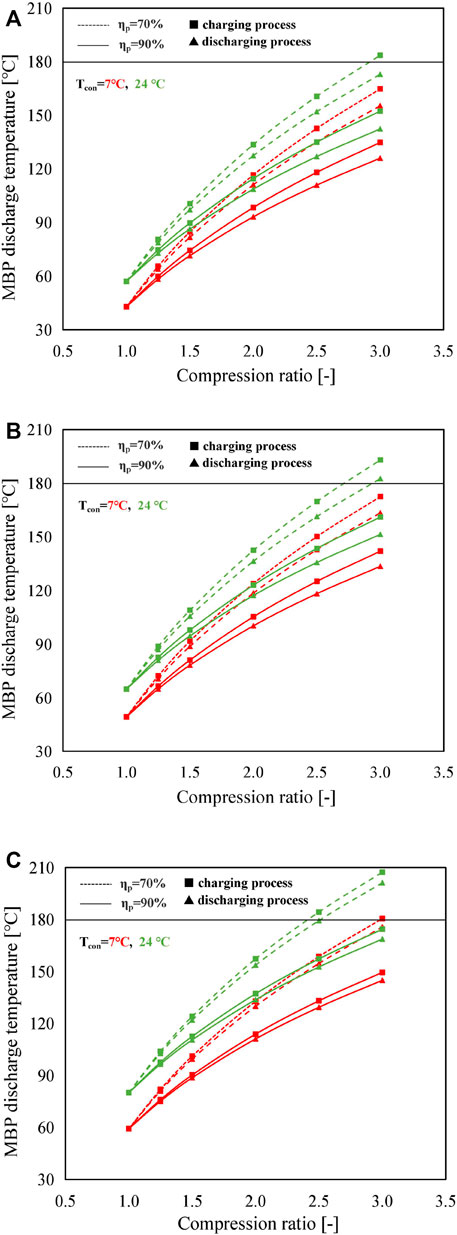
FIGURE 5. Variation of MBP discharge temperature with the compression ratio by using (A) SrBr2·H2O/H2O, (B) LiOH/H2O, and (C) CaCl2·H2O/H2O as the working pair at different operating conditions (solid lines with triangles and squares represent the discharging process and charging process at an isentropic efficiency of 90%, respectively; dashed lines with triangles and squares represent the discharging process and charging process at an isentropic efficiency of 70%, respectively).
3.2 Comparison of Energy Efficiency
Figure 6 illustrates the variations of electricity consumption of the MBP and COPelec in the A mode and B mode with compression ratios for different MBP isentropic efficiencies. The condensing temperature and reaction advancement are kept constant as 7°C and 1, respectively. With the increase of compression ratio, the electricity consumptions increase while COPelecs decrease. It can be noticed that the COPelecs obtained with the A mode are slightly lower than those obtained with the B mode, but the difference is marginal. There are two reasons accountable for this difference. The first is that the electricity consumption in the A mode is higher than that in the B mode, as can be observed from Figure 6. The second is that the amount of heat released from the reactor during the discharging process in the B mode increases with the compression ratio and is larger than that in the A mode which remains constant, as illustrated in Supplementary Figure S1. The reason behind the increase in the amount of heat released in the B mode is that the rise in the MBP discharge temperature, as discussed above and shown in Figure 5, contributes to the reduction of heat load requirement for the preheating process of ①→④, while the high-temperature discharge vapor from the MBP in the charging process is condensed in the condenser, releasing directly its sensible and latent heat to the ambient environment. Furthermore, as the compressor efficiency increases, the electricity consumption reduces. The magnitude of this reduction becomes more evident with the increase in compression ratio, representing the same trend as the MBP discharge temperature mentioned above.
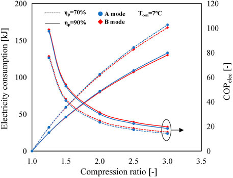
FIGURE 6. Variations of MBP electricity consumption and COPelec in the A mode and B mode using SrBr2·H2O/H2O as a working pair with the compression ratio at Tcon = 7°C and ηr = 1 (solid lines represent the isentropic efficiency of the MBP is 90%; dashed lines indicate the isentropic efficiency of the MBP is 70%; and blue and red indicate the A mode and B mode, respectively.).
Figure 7 depicts the electricity consumption and COPelec of B and C modes under various operating conditions. The electricity consumption of the C mode is the sum of A and B modes, approximately two times higher than that of the B mode (Figure 7A), leading to a degradation in COPelec of about 50%, as shown in Figure 7B. Taking Tcon = 7°C, ηp = 70%, and Cr = 2 as an example, the electricity consumption in the B mode and C mode is 103 and 207 kJ, with the corresponding COPelec of 24.6 and 12.2, respectively.
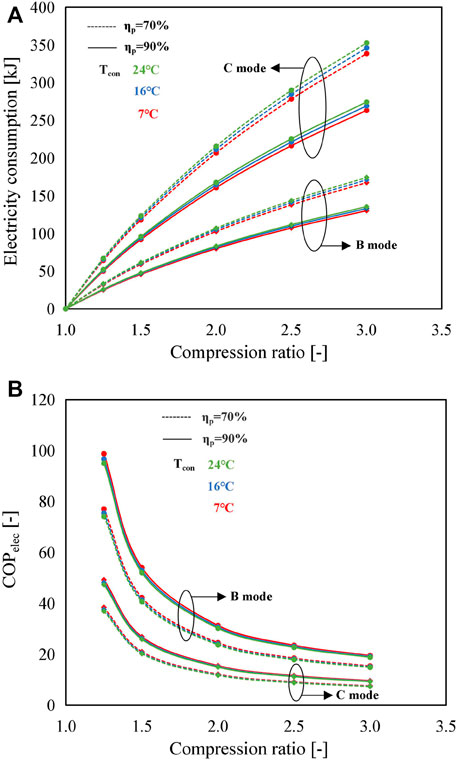
FIGURE 7. Influence of compression ratio on (A) electricity consumption and (B) COPelec for the B mode and C mode using SrBr2·H2O/H2O as the working pair under different condensing temperatures and MBP isentropic efficiencies.
The dependence of COPelec and electricity consumption of MBP on the compression ratio for different working pairs at different condensing temperatures in the B mode is shown in Figure 8. According to Figure 8A, the electricity consumption follows the order of LiOH/H2O > SrBr2·H2O/H2O > CaCl2·H2O/H2O under the same operating condition. This is because, as stated above, the mass of the three types of reactive salt is assumed to be 2 kg, resulting in the molar amount of water vapor (ΔNH2O) reacted at the reaction advancement of 1 to be 37.7, 47.7, and 15.5 mol for SrBr2·H2O, LiOH/H2O, and CaCl2·H2O, respectively. The higher the ΔNH2O, the larger the electricity consumption. Although the higher suction temperature of the MBP, i.e., the evaporating temperature/heat source temperature (CaCl2·H2O/H2O > LiOH/H2O > SrBr2·H2O/H2O as presented in Figure 4), also contributes to the increase of electricity consumption, ΔNH2O has a more significant influence, according to Eq. 11. In addition, for the same working pair, a higher condensing temperature leads to larger electricity consumption at the same compression ratio due to the requirement of a higher evaporating temperature.
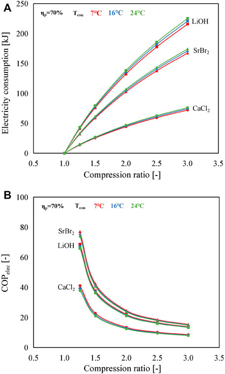
FIGURE 8. Influence of compression ratio on (A) the electricity consumption of the MBP and (B) COPelec in the B mode with an isentropic efficiency of 70% for different working pairs at different condensing temperatures.
For each case, an increase in the compression ratio leads to a decrease in COPelec due to the increase of electricity consumption of the MBP, as illustrated in Figure 8B. Unlike variation tendencies in electricity consumption, SrBr2·H2O/H2O exhibits the highest COPelec value, while CaCl2·H2O/H2O shows the smallest value, although it consumes the lowest electric power. The reason is that, as discussed above, the amount of heat output of CaCl2·H2O/H2O is much smaller than that of the other two working pairs at the given operating conditions. Furthermore, the condensing temperature has a negligible effect on COPelec, especially under the large compression ratio, due to the much higher amount of heat output compared to electricity consumption. This further demonstrates that the proposed system can achieve satisfactory performance by sacrificing a small amount of electric energy.
In conclusion, values of COPelec in A and B modes maintain a comparatively higher level, ranging from 7.04 (CaCl2·H2O/H2O) to 13.72 (SrBr2·H2O/H2O) for the A mode and from 8.01 (CaCl2·H2O/H2O) to 14.92 (SrBr2·H2O/H2O) for the B mode under the operating conditions of Cr = 3, Tcon = 24°C, and ηr = 3. Concerning the C mode, the COPelec values are smaller than those of the other two modes, varying from 3.98 (CaCl2·H2O/H2O) to 7.37 (SrBr2·H2O/H2O), which are still comparable to the conventional heat pump system.
Figure 9 plots the variation tendencies of COPtotal for three different working pairs in different operating modes. By comparing Figures 9A–C, it can be observed that, for the A mode, a slight decline in COPtotal with the compression ratio can be observed in the three working pairs. In contrast, COPtotals improve as the compression ratio increases in the B mode due to the positive contribution of high-temperature discharge vapor of the MBP to the heat output, as described in Figure 5. Under the combined influence of two MBPs (one in the charging process and the other in the discharging process), a slight increase of COPtotal in the C mode is detected. Furthermore, the variation tendencies of COPtotal with the change in condensing temperature when using SrBr2·H2O/H2O or LiOH/H2O as the working pair are similar, i.e., increases with an increase in condensing temperature, while CaCl2·H2O/H2O exhibits an opposite trend. The primary cause is that the temperature differences between the heat output and the ambient temperature in the discharging process (ΔT3 = T4−T2) and between the heat source and the condenser in the charging process (ΔT4 = T1−T2) decline with the increase in condensing temperature for SrBr2·H2O/H2O and LiOH/H2O. Taking the SrBr2·H2O/H2O pair employed in the B mode as an instance, ΔT3 and ΔT4 decrease from 65 to 59°C and from 36 to 33°C as the condensing temperature changes from 7 to 24°C, respectively, resulting in the reduction of Qsalt and Q1 according to Eqs 8–16. Despite the electricity consumption of the MBP rising with the condensing temperature, as shown in Figure 8A, the total energy input (the denominator of Eq. 19) decreases, leading to the increase of COPtotal. As for the CaCl2·H2O/H2O pair, however, ΔT3 and ΔT4 increase from 115 to 122°C and from 52 to 56°C as the condensing temperature rises from 7 to 24°C, respectively, leading to the increment of Qsalt and Q1 and, thus, the decrease of COPtotal corresponding to Eq. 19.
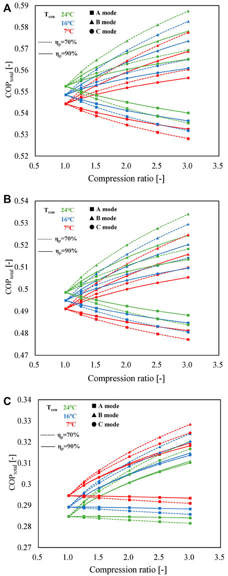
FIGURE 9. Influence of compression ratio on COPtotal for A (lines with squares), B (lines with triangles), and C (lines with circles) modes using (A) SrBr2·H2O/H2O, (B) LiOH/H2O, and (C) CaCl2·H2O/H2O as working pairs under different operating conditions (solid lines represent the isentropic efficiency of the MBP is 90%; dashed lines indicate the isentropic efficiency of the MBP is 70%; and red, blue, and green denote the condensing temperature of 7, 16, and 24°C, respectively).
Moreover, it can be found that COPtotals decrease as a function of increasing isentropic efficiency of MBP in B and C modes, while the opposite holds for A mode. In addition, the difference induced by MBP isentropic efficiency increases with the growth of compression ratio. This phenomenon can be attributed to the recovery of heat contained in the discharge vapor of the MBP, as discussed in Figure 5. The variation ranges of COPtotal and COPelec values at Cr = 3 and ηp = 70% are 0.53∼0.59 and 7.4∼19.6 for SrBr2·H2O/H2O, 0.48∼0.53 and 6.6∼17.5 for LiOH/H2O, and 0.28∼0.33 and 4.0∼8.6 for CaCl2·H2O/H2O, respectively. On the whole, under the conditions that the conventional mode cannot work, the three proposed modes can acquire satisfied and relatively stable COPtotal by sacrificing a small amount of electric energy. Moreover, the COPelec value is comparable to that of the heat pump system.
3.3 Comparison of Exergy Efficiency
The exergy efficiencies of different modes using different working pairs at varying compression ratios are presented in Figure 10. Reaction advancement is set as 1. It can be seen that lower MBP isentropic efficiency contributes to lower exergy efficiency because of higher electric power consumed. For instance, when using SrBr2·H2O/H2O as the working pair, the decline in exergy efficiency is 7.5%, 5.9%, and 11.7% for A, B, and C modes, respectively, whereas isentropic efficiency suffers a decrease from 90% to 70% at Tcon = 24°C and Cr = 3.
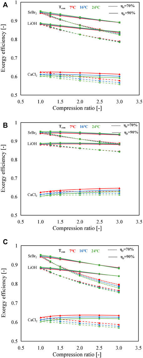
FIGURE 10. Comparisons of exergy efficiencies under different compression ratios and condensing temperatures for the three working pairs: (A) A mode, (B) B mode, and (C) C mode (solid lines represent the isentropic efficiency of the MBP is 90%; dashed lines indicate the isentropic efficiency of the MBP is 70%; and red, blue, and green denote the condensing temperature of 7, 16, and 24°C, respectively).
By comparing Figures 10A∼C, it can be observed that the exergy efficiency of SrBr2·H2O/H2O and LiOH/H2O working pairs tend to deteriorate with an increase in compression ratio in both A and B modes, thus resulting in the decrease in the C mode which is even more pronounced. Taking Tcon = 24°C and ηp = 70% as an example, the exergy efficiencies of A, B, and C modes using SrBr2·H2O/H2O decrease from 0.95 to 0.82, 0.88, and 0.78 (corresponding to the drop rates of 15.3%, 7.9%, and 22.3%), respectively, with the increase in compression ratio from 1.0 to 3.0. Compared to the A mode, a relatively slight reduction of exergy efficiency can be observed in the B mode for SrBr2·H2O/H2O and LiOH/H2O, primarily due to the lower electricity consumption and higher heat output.
It can be found that reversal points exist in all three modes when employing SrBr2·H2O/H2O or LiOH/H2O as working pairs. On the left side of the reversal point, the exergy efficiency slightly increases with the condensing temperature. In contrast, on the right side, higher condensing temperature causes lower exergy efficiency. It suggests that the higher the condensing temperature is, the more significant the reduction in exergy efficiency is with an increase in compression ratio due to greater electric power consumed, as depicted in Figure 8A. Also, the reversal point appears in a lower compression ratio region when the MBP isentropic efficiency is low. As an illustration, the reversal points are located in the compression ratio range of 1.25∼1.5 and 2.0∼2.5 for the C mode with an MBP isentropic efficiency of 70% and 90% when using SrBr2·H2O/H2O as the working pair, respectively, as indicated in Figure 10C. This could be attributed to the following aspects. On the one hand, the higher condensing temperature leads to lower exergy output due to T2/T4 (i.e., the temperature ratio of the condenser to heat output) getting larger. On the other hand, the increase of condensing temperature will also result in the decline of exergy input caused by the heat transfer (i.e., the first and the second term of the denominator in Eq. 21), owing to the increase in T2/T1 and T2/T3 and the increase in electricity consumption. Although the exergy input by heat transfer plays the principal role in the variation of exergy input, i.e., the total exergy input decreases with condensing temperature, the electricity consumption is accounted for an increase in the proportion of total exergy input with the increase in condensing temperature and compression ratio. The increase in electricity consumption leads to a lower reducing rate of total exergy input than the exergy output at the high-compression ratio region and, therefore, the decrease in exergy efficiency. On the contrary, in the low-compression ratio region, the reduction in the total exergy input is more significant than that in the exergy output due to the effect of increasing electricity consumption on the reducing rate of total exergy input being less marked. This effect, however, will be enhanced with the descent of MBP isentropic efficiency. A similar behavior can be observed for LiOH/H2O.
In contrast, for CaCl2·H2O/H2O, the decline in condensing temperature gives rise to the enhancement of exergy efficiency, and no reversal point exists, which is consistent with that of the COPtotal, as shown in Figure 10. This is because when the condensing temperature increases, the output exergy decreases, while the input exergy increases in all conditions. In addition, it can be found from Figure 10B that the increase in the compression ratio has a negligible influence on the exergy efficiency of CaCl2·H2O/H2O in the B mode, owing to the output and input exergy sharing a close increasing rate with the compression ratio (as depicted in Supplementary Figure S2). This variation tendency differs from that observed in the A mode, whose output exergy remains constant (A mode) while the input exergy increases with the compression ratio due to the increase in electricity consumption.
It can be observed that the exergy efficiencies of the working pairs follow the same order as COPs under the same operating condition, i.e., SrBr2·H2O/H2O (0.78∼0.95) > LiOH/H2O (0.75∼0.89) > CaCl2·H2O/H2O (0.56∼0.60). The explanation for the poor exergy efficiency value of CaCl2·H2O/H2O is two-fold. One aspect is its small amount of heat output leads to smaller output exergy. The other aspect is the relatively higher heat input needed during the charging process and the higher temperature difference between the heat source and the condenser, bringing about larger input exergy.
3.4 Influence of Reaction Advancement
In this section, the influence of the reaction advancement on performance indicators is investigated, taking the B mode using SrBr2·H2O/H2O as the working pair as a representative.
Figure 11 exhibits the influence of reaction advancement on COPelec and COPtotal of the B mode employing SrBr2·H2O/H2O as the working pair under various operating conditions. As shown in Figure 11A, the COPelec indicates a rapid increase at first and then gradually increases with the reaction advancement. This is because the fractional change in the heat output with reaction advancement, which is expressed as α = (Qout,2-Qout,1)/Qout,1 (where Qout,2 and Qout,1 are the amount of heat output at the reaction advancement of ηr,2 and ηr,1, respectively, e.g., ηr,2 = 0.15 and ηr,1 = 0.10), is much higher than that of the electricity consumption, which is expressed as β = (Wp,2−Wp,1)/Wp,1 (where Wp,2 and Wp,1 denote the amount of electricity consumption at the reaction advancement of ηr,2 and ηr,1, respectively), at the lower reaction advancement range (ηr < 0.2), as illustrated in Supplementary Figure S3. However, the difference between these two fractional changes becomes smaller when the reaction advancement is larger than 0.2.
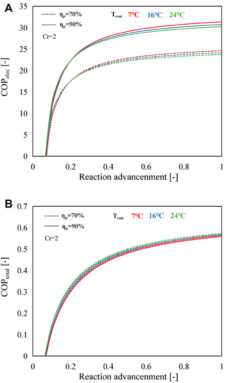
FIGURE 11. Variations in (A) COPelec and (B) COPtotal with reaction advancement using SrBr2·H2O/H2O as the working pair at different condensing temperatures and MBP isentropic efficiencies.
The higher condensing temperature leads to a higher COPelec when the reaction advancement is lower than 0.2; otherwise, the higher condensing temperature gives rise to a lower COPelec. The main reason for this trend is that the ratio of heat output at different condensing temperatures is inferior to that of electricity consumption when the reaction advancement is under 0.2. For instance, as shown in Supplementary Figure S4, the ratio of heat output at 7°C (Qout,7°C) to heat output at 24°C (Qout,24°C) is smaller than the ratio of electricity consumption at 7°C (Wp,7°C) to electricity consumption at 24°C (Wp,24°C) when ηr < 0.2, resulting in higher COPelec value at higher condensing temperature. Nevertheless, the situation is reversed when the reaction advancement exceeds 0.2, i.e., Qout,7°C`/Qout,24°C is greater than Wp,7°C/Wp,24°C, implying that the amount of heat output plays a more critical role in COPelec rather than the electricity consumption of MBP.
It is observed from Supplementary Figure S5A that the LiOH/H2O working pair has the same tendency as that in SrBr2·H2O/H2O. However, this variation trend does not appear when using CaCl2·H2O/H2O as the working pair as a lower condensing temperature contributes to a higher COPelec within the whole range of reaction advancement, as illustrated in Supplementary Figure S5B. This is due to the higher amount of heat output and minor electricity consumption under the lower-condensing temperature condition than the higher one (Supplementary Figure S6C).
Similarly, COPtotal increases with the reaction advancement, as illustrated in Figure 11B. The COPtotal slightly increases with the higher condensing temperature, resulting from a minor temperature difference between the heat source and the condenser that reduces the heat load needed to preheat the working pairs. Compared to COPelec, COPtotal is little affected by the isentropic efficiency of the MBP due to the amount of heat output being higher at lower isentropic efficiency that counteracts the adverse effect of increased electricity consumption. Furthermore, it can be seen from Supplementary Figure S7 that, under the same operating conditions, the heat outputs in mode B with different compression ratios are high when compared with the conventional mode over the whole range of reaction advancement. As a consequence, the COPtotals are larger, as illustrated in Figure 12A.
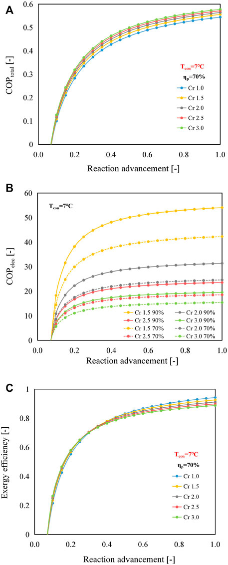
FIGURE 12. Effect of reaction advancement on (A) COPtotal, (B) COPelec, and (C) ηex of the B mode using SrBr2·H2O/H2O as the working pair at the condensing temperature of 7°C and MBP isentropic efficiency of 70%.
Because of the limited heat and mass transfer performance, the reaction advancement is commonly regulated in the range from 0.7 to 0.9 under practical operating conditions (Jiang et al., 2020). Within this range, COPtotals of the B mode could be enhanced by 2%–7% when the compression ratio varies from 1.5 to 3.0, compared with those of the conventional mode, as indicated in Figure 12A. It can be observed that the values of COPelec and COPtotal are less than 0 when the reaction advancement is smaller than about 0.1. This phenomenon is because the sum of the heat required to preheat the reactant salt and the discharge vapor of the MBP, i.e., the second and third terms on the right-hand side of Eq. 10, is greater than the reaction heat (the first term on the right-hand side). A similar phenomenon is observed in the other two working pairs, as shown in Supplementary Figures S8, S9. Still, in the case of CaCl2·H2O/H2O, the reaction advancement needs to be larger than 0.35 to make the reactor release heat properly, mainly because the heat required to warm the reactant salt is significantly higher than the heat output when the reaction advancement is lower than 0.35. The main reason for the higher heat demand on the CaCl2·H2O/H2O pair is that the heat output temperature is much larger than that of the other two working pairs (e.g., 72, 87, and 122°C for SrBr2·H2O/H2O, LiOH/H2O, and CaCl2·H2O/H2O, respectively, at the condensing temperature of 7°C, as shown in Supplementary Figure S10), contributing to a greater temperature difference (T4 − T2) as indicated in Eq. 8.
With the extension of reaction advancement, COPelec increases significantly when the reaction advancement is less than 0.2, followed by a gradual increase, as illustrated in Figure 12B. Due to relatively low electricity consumption, the lower compression ratio and better MBP isentropic efficiency result in higher COPelec. Under this scenario, the maximum and minimum values of COPelec at the reaction advancement of 0.8 and the MBP isentropic efficiency of 70% are 41.3 (Cr = 1.5) and 15.2 (Cr = 3.0), respectively, and they remain at relatively high levels.
As demonstrated in Figure 12C, a higher compression ratio favors larger exergy efficiency when the reaction advancement is below 0.35; however, a higher compression ratio reduces exergy efficiency as the reaction advancement is before 0.35. In addition, the exergy efficiency differences between the B mode and the conventional mode increase with the increment of reaction advancement. The primary reason is that, for the B mode, although both the values of input and output exergies increase with reaction advancement, the increase is more pronounced in the former for reaction advancement greater than 0.35, as shown in Supplementary Figure S11A. Instead, the conventional mode shows the opposite pattern, i.e., the rise in the exergy output is more marked. The reason for the different behaviors of these two modes is that the electricity consumption of the MBP in the B mode utilizing SrBr2·H2O/H2O as the working pair a growing share of the input exergy with the increasing reaction advancement and compression ratio. Furthermore, it becomes increasingly prominent when the MBP isentropic efficiency declines. Supplementary Figure S12 presents the exergy efficiency of the B mode (SrBr2·H2O/H2O) with a higher MBP isentropic efficiency of 90%. It can be seen that the exergy efficiencies are enhanced, and the reversal point is elevated to about 0.75. In addition, the difference in exergy efficiency between the B mode and conventional mode becomes less noticeable when the reaction advancement exceeds the reversal point. The same behavior is also observed in the LiOH/H2O working pair (data not shown).
However, no reversal point is observed for CaCl2·H2O/H2O due to both operating modes’ input and output exergy change at a relatively stable rate, as displayed in Supplementary Figure S5B. In addition, it can be found that CaCl2·H2O/H2O has the lowest output exergy, while LiOH/H2O has the highest among the three working pairs. This is mainly because LiOH/H2O has the largest amount of heat output (2886 kJ), followed by SrBr2·H2O/H2O (2503 kJ) and CaCl2·H2O/H2O (587 kJ) under the operating conditions of Tcon = 7°C, ηp = 90%, Cr = 2, and ηr = 1, as shown in Supplementary Figure S6, even though CaCl2·H2O/H2O has the highest heat output temperature (122°C, Supplementary Figure S10).
For the A mode using the SrBr2·H2O/H2O working pair, as shown in Supplementary Figure S13A, the exergy efficiencies are all inferior to that of the conventional one. The decline observed in the exergy efficiency is attributed to the electricity consumption of the MBP in the charging process that made no contribution to the output exergy, unlike the B mode, as demonstrated in Figure 12C, although there is an effect on the reduction in the charging temperature and, thus, a lower input exergy; however, electricity consumption has an increasing impact on the input exergy with exergy efficiency and compression ratio, finally resulting in a higher input exergy (Supplementary Figure S13B). It can be seen from Supplementary Figure S14 that there is little difference between the A mode and conventional mode when employing CaCl2·H2O/H2O at the MBP isentropic efficiency of 90% owing to the fact that the positive and negative effects of the MBP on the input exergy counteract each other.
4 Conclusion
To facilitate efficient utilization of low-grade thermal energy that the conventional TCES system cannot utilize, three MBP-assisted TCES operating modes using SrBr2·H2O/H2O, LiOH/H2O, and CaCl2·H2O/H2O as working pairs are proposed for the application of heat storage and upgrading. The operating principles and advances of the proposed modes compared with the conventional mode are expounded. A detailed thermodynamic model is established, and the influences of critical operating parameters on the system performances are investigated theoretically. The salient conclusions are summarized as follows:
(1) Contrary to the conventional mode, in which the charging or discharging process cannot proceed when the low-grade heat temperature is not high enough, the proposed modes enable normal operation with the assistance of an MBP driven by electrical power, making system output more stable and flexible to meet the diverse requirements of the demand side. The heat source temperature for different working pairs can be minimized by up to 21∼25°C by employing the B mode with a compression ratio of 3.0 at the condensing temperature of 24°C.
(2) By investing a small quantity of electric energy, the proposed modes can achieve satisfied COPtotal values with the operating conditions under which the conventional mode cannot work. Furthermore, the COPelec values are comparable to those of the conventional heat pumps. The variation ranges of COPtotal and COPelec values at ηp = 1 and ηp = 70% are 0.53∼0.59 and 7.4∼19.6 for SrBr2·H2O/H2O, 0.48∼0.53 and 6.6∼17.5 for LiOH/H2O, and 0.28∼0.33 and 4.0∼8.6 for CaCl2·H2O/H2O, respectively.
(3) From the exergy perspective, A and B modes perform much better than the C mode due to the lower electric power consumption. SrBr2·H2O/H2O exhibits the highest exergy efficiency of 0.78∼0.95, followed by LiOH/H2O (0.75∼0.89) and CaCl2·H2O/H2O (0.56∼0.62) at ηp = 1 and ηp = 70%.
(4) There is a maximum permitted value of Cr (corresponding to a lower limit of heat source temperature) which is determined by the operating modes, conditions, and working pairs to guarantee that the discharge temperature of MBP does not exceed the maximum allowable value of 180°C. Under the given conditions, the proposed modes with SrBr2·H2O/H2O can practically function normally, maintaining the MBP discharge temperature below safe limits.
(5) Compared with the A mode, the B mode is more effective in reducing the driving temperature as well as achieving better system performance, such as applications aiming to achieve a stable heat output while keeping the heat source temperature low. In comparison, the C mode is preferable for situations requiring lower heat source temperature in both charging and discharging processes.
(6) Among the three working pairs, SrBr2·H2O/H2O has the best system performance both from energetic and exergetic perspectives, while CaCl2·H2O/H2O shows the lowest values. However, on the other hand, CaCl2·H2O/H2O is better suited to applications requiring higher output temperatures, implying that a trade-off must be made between heat output temperature and system performance.
In conclusion, the proposed modes are promising approaches compared to the conventional mode due to the significant improvement in the operating range of heat source temperature, which, in turn, demonstrates their ability to cope with the unstable low-grade heat source and improve energy efficiency. The findings of this study can provide theoretical references and recommendations for choosing MBP-assisted TCES modes, operating conditions, and working pairs to use low-grade heat energy for heat storage and upgrading.
Data Availability Statement
The original contributions presented in the study are included in the article/Supplementary Material, further inquiries can be directed to the corresponding authors.
Author Contributions
TZ: theoretical research, write up, and review. JL: conception and supervision. LD: interpretation of data. ZH: methodology. NK: critical review and content suggestions. RW: editing and proofreading. HH: funding acquisition and supervision. All authors have read and agreed to the published version of the manuscript.
Funding
This work was supported by the Key Special Project for Introduced Talents Team of Southern Marine Science and Engineering Guangdong Laboratory (Guangzhou) (GML2019ZD0108), the Key Research Program of Frontier Sciences, Chinese Academy of Sciences (QYZDY-SSW-JSC038), the Key Laboratory of Renewable Energy, Chinese Academy of Sciences (E1290401), the Science and Technology Program of Guangzhou, China (E1310404), and the Science and Technology project of China Energy Investment Corporation (GJNY-20-121).
Conflict of Interest
The authors declare that the research was conducted in the absence of any commercial or financial relationships that could be construed as a potential conflict of interest.
Publisher’s Note
All claims expressed in this article are solely those of the authors and do not necessarily represent those of their affiliated organizations, or those of the publisher, the editors, and the reviewers. Any product that may be evaluated in this article, or claim that may be made by its manufacturer, is not guaranteed or endorsed by the publisher.
Supplementary Material
The Supplementary Material for this article can be found online at: https://www.frontiersin.org/articles/10.3389/fenrg.2022.851611/full#supplementary-material
References
Abernathy, S. M., and Brown, K. R. (2015). Using the Vapor Pressure of Pure Volatile Organic Compounds to Predict the Enthalpy of Vaporization and Computing the Entropy of Vaporization. OALib 02, 1–7. doi:10.4236/oalib.1101927
Bao, H., Ma, Z., and Roskilly, A. P. (2016). Integrated Chemisorption Cycles for Ultra-low Grade Heat Recovery and Thermo-Electric Energy Storage and Exploitation. Appl. Energ. 164, 228–236. doi:10.1016/j.apenergy.2015.11.052
Cal-Chlor Corporation (2018). Calcium Chloride - A Guide to Physical Properties. Available at: https://www.oxy.com/OurBusinesses/Chemicals/Products/Documents/CalciumChloride/173-01791.pdf (Accessed July 11, 2021).
Cammarata, A., Verda, V., Sciacovelli, A., and Ding, Y. (2018). Hybrid Strontium Bromide-Natural Graphite Composites for Low to Medium Temperature Thermochemical Energy Storage: Formulation, Fabrication and Performance Investigation. Energ. Convers. Manage. 166, 233–240. doi:10.1016/j.enconman.2018.04.031
Cengel, Y. A., and Boles, M. A. (2015). Thermodynamics: An Engineering Approach. 8th ed. New York: McGraw-Hill.
Courbon, E., D'Ans, P., Permyakova, A., Skrylnyk, O., Steunou, N., Degrez, M., et al. (2017a). A New Composite Sorbent Based on SrBr2 and Silica Gel for Solar Energy Storage Application with High Energy Storage Density and Stability. Appl. Energ. 190, 1184–1194. doi:10.1016/j.apenergy.2017.01.041
Courbon, E., D'Ans, P., Permyakova, A., Skrylnyk, O., Steunou, N., Degrez, M., et al. (2017b). Further Improvement of the Synthesis of Silica Gel and CaCl2 Composites: Enhancement of Energy Storage Density and Stability over Cycles for Solar Heat Storage Coupled with Space Heating Applications. Solar Energy 157, 532–541. doi:10.1016/j.solener.2017.08.034
Engineering ToolBox (2003). Gases - Ratios of Specific Heat. Available at: https://www.engineeringtoolbox.com/specific-heat-ratio-d_608.html (Accessed July 18, 2021).
Engineering ToolBox (2004). Water - Specific Heat vs. Temperature. Available at: https://www.engineeringtoolbox.com/specific-heat-capacity-water-d_660.html (Accessed June 1, 2021).
Ferrucci, F., Stitou, D., Ortega, P., and Lucas, F. (2018). Mechanical Compressor-Driven Thermochemical Storage for Cooling Applications in Tropical Insular Regions. Concept and Efficiency Analysis. Appl. Energ. 219, 240–255. doi:10.1016/j.apenergy.2018.03.049
Fitó, J., Coronas, A., Mauran, S., Mazet, N., Perier-Muzet, M., and Stitou, D. (2019). Hybrid System Combining Mechanical Compression and Thermochemical Storage of Ammonia Vapor for Cold Production. Energ. Convers. Manage. 180, 709–723. doi:10.1016/j.enconman.2018.11.019
Fopah-Lele, A., and Tamba, J. G. (2017). A Review on the Use of SrBr2·6H2O as a Potential Material for Low Temperature Energy Storage Systems and Building Applications. Solar Energ. Mater. Solar Cell 164, 175–187. doi:10.1016/j.solmat.2017.02.018
Forster, P. M., Forster, H. I., Evans, M. J., Gidden, M. J., Jones, C. D., Keller, C. A., et al. (2020). Current and Future Global Climate Impacts Resulting from COVID-19. Nat. Clim. Chang. 10, 913–919. doi:10.1038/s41558-020-0883-0
Gao, P., Shao, L.-L., and Zhang, C.-L. (2019). Pressure Boost Thermochemical Sorption Heat Pump Cycle. Energy 169, 1090–1100. doi:10.1016/j.energy.2018.12.119
Gao, P., Wang, L. W., and Zhu, F. Q. (2021). A Novel Hybrid Solid Sorption-Compression Refrigeration Technology for Refrigerated Transportation and Storage. Int. J. Refrigeration 122, 1–10. doi:10.1016/j.ijrefrig.2020.10.041
Glasser, L. (2014). Thermodynamics of Inorganic Hydration and of Humidity Control, with an Extensive Database of Salt Hydrate Pairs. J. Chem. Eng. Data 59 (2), 526–530. doi:10.1021/je401077x
Goetz, V., Elie, F., and Spinner, B. (1993). The Structure and Performance of Single Effect Solid-Gas Chemical Heat Pumps. Heat Recovery Syst. CHP 13 (1), 79–96. doi:10.1016/0890-4332(93)90027-S
Hawwash, A. A., Hassan, H., and Feky, K. E. (2020). Impact of Reactor Design on the thermal Energy Storage of Thermochemical Materials. Appl. Therm. Eng. 168, 114776. doi:10.1016/j.applthermaleng.2019.114776
Hong, H., Li, W., and Gu, C. (2018). Performance Study on a Mechanical Vapor Compression Evaporation System Driven by Roots Compressor. Int. J. Heat Mass Transfer 125, 343–349. doi:10.1016/j.ijheatmasstransfer.2018.03.098
Hu, B., Wu, D., and Wang, R. Z. (2018). Water Vapor Compression and its Various Applications. Renew. Sust. Energ. Rev. 98, 92–107. doi:10.1016/j.rser.2018.08.050
International Energy Agency (IEA) (2020a). Coal 2020 Analysis and Forecast to 2025. Available at: https://www.iea.org/reports/coal-2020 (Accessed October 9, 2021).
International Energy Agency (IEA) (2020b). Global Energy Review 2020. Available at: https://www.iea.org/reports/global-energy-review-2020 (Accessed September 5, 2021).
Ivanova, I. (2020). Greenhouse Gas Emissions Around the World Nearly Back to Pre-pandemic Levels. Available at: https://www.cbsnews.com/news/greenhouse-gas-emissions-pre-coronavirus-pandemic-levels/ (Accessed October 12, 2021).
Jabbari-Hichri, A., Bennici, S., and Auroux, A. (2017). CaCl2-containing Composites as Thermochemical Heat Storage Materials. Solar Energ. Mater. Solar Cell 172, 177–185. doi:10.1016/j.solmat.2017.07.037
Jiang, L., Wang, R. Q., Tao, X., and Roskilly, A. P. (2020). A Hybrid Resorption-Compression Heat Transformer for Energy Storage and Upgrade with a Large Temperature Lift. Appl. Energ. 280, 115910. doi:10.1016/j.apenergy.2020.115910
Jiang, L., Wang, R. Z., Wang, L. W., and Roskilly, A. P. (2017). Investigation on an Innovative Resorption System for Seasonal thermal Energy Storage. Energ. Convers. Manage. 149, 129–139. doi:10.1016/j.enconman.2017.07.018
Johannes, K., Kuznik, F., Hubert, J.-L., Durier, F., and Obrecht, C. (2015). Design and Characterisation of a High Powered Energy Dense Zeolite thermal Energy Storage System for Buildings. Appl. Energ. 159, 80–86. doi:10.1016/j.apenergy.2015.08.109
Kayode Coker, A. (2015). Ludwig's Applied Process Design for Chemical and Petrochemical Plants. 4th ed. United States: Gulf Professional Publishing.
Kubota, M., Matsumoto, S., Matsuda, H., Huang, H. Y., He, Z. H., and Yang, X. X. (2014). Chemical Heat Storage with LiOH/LiOH·H2O Reaction for Low-Temperature Heat below 373 K. Amr 953-954, 757–760. doi:10.4028/www.scientific.net/amr.953-954.757
Lahmidi, H., Mauran, S., and Goetz, V. (2006). Definition, Test and Simulation of a Thermochemical Storage Process Adapted to Solar thermal Systems. Solar Energy 80, 883–893. doi:10.1016/j.solener.2005.01.014
Li, L., Li, S., Zeng, T., Deng, L., Huang, H., Li, J., et al. (2021). Comparative Analysis of 3D Graphene-LiOH·H 2 O Composites by Modification with Phytic Acid and Ascorbic Acid for Low‐Grade Thermal Energy Storages. Energy Technol. 9, 2001086. doi:10.1002/ente.202001086
Li, W., Klemeš, J. J., Wang, Q., and Zeng, M. (2020). Energy Storage of Low Potential Heat Using Lithium Hydroxide Based Sorbent for Domestic Heat Supply. J. Clean. Prod. 285, 124907. doi:10.1016/j.jclepro.2020.124907
Liu, H., Wang, W., and Zhang, Y. (2021). Performance gap between Thermochemical Energy Storage Systems Based on Salt Hydrates and Materials. J. Clean. Prod. 313, 127908. doi:10.1016/j.jclepro.2021.127908
Livent (2018). Lithium Hydroxide Monohydrate Purified. Available at: https://livent.com/wp-content/uploads/2018/09/QS-PDS-1064-r1-1.pdf (Accessed June 3, 2021).
Lu, Z. (2019). Analysis on Current Situation of Industrial Waste Heat Recovery in China. Equipment Manufacturing Tech. 12, 204–206.
Park, J., Han, S. C., Jang, H. Y., Lee, S. M., Lee, P. S., and Lee, J. Y. (2002). The Development of Compressor-Driven Metal Hydride Heat Pump (CDMHHP) System as an Air Conditioner. Int. J. Hydrog. Energ. 27 (9), 941–944. doi:10.1016/S0360-3199(01)00187-2
Tao, Y., Lee, H., Hwang, Y., Radermacher, R., and Wang, C. (2015). Electrochemical Compressor Driven Metal Hydride Heat Pump. Int. J. Refrigeration 60, 278–288. doi:10.1016/j.ijrefrig.2015.08.018
United Nations Framework Convention on Climate Change (2015). Decision 1/CP.21, Paris Agreement, Document FCCC/CP/2015/10/Add.1. Paris: United Nations. Available at: https://www.un.org/en/development/desa/population/migration/generalassembly/docs/globalcompact/FCCC_CP_2015_10_Add.1.pdf (Accessed October 1, 2021).
Van der Pal, M., de Boer, R., Wemmers, A., Smeding, S., Veldhuis, J., and a Nijeholt, J. A. L. (2013). “Experimental Results and Model Calculations of a Hybrid Adsorption-Compression Heat Pump Based on a Roots Compressor and Silica Gel-Water Sorption,” in Thermally Driven Heat Pumps for Heating and Cooling. Berlin: Universitätsverlag der TU Berlin, 161–171. Available at: https://depositonce.tu-berlin.de/handle/11303/4023.
Van der Pal, M., Wemmers, A., Smeding, S., and Van den Heuvel, K. (2011). Study on the Performance of Hybrid Adsorption-Compression Type II Heat Pumps Based on Ammonia Salt Adsorption. Int. J. Low-carbon Technol. 6 (3), 207–211. doi:10.1093/ijlct/ctr009
Zeng, C., Liu, S., Shukla, A., Yang, L., Han, X., and Shen, Y. (2021). Numerical Modelling of the Operational Effects on the Thermochemical Reactor Performance. Energy and Buildings 230, 110535. doi:10.1016/j.enbuild.2020.110535
Keywords: thermochemical heat storage, low-grade heat, mechanical booster pump, thermodynamic analysis, heat upgrading
Citation: Zeng T, Li J, Deng L, He Z, Kobayashi N, Wu R and Huang H (2022) Mechanical Booster Pump-Assisted Thermochemical Mode for Low-Grade Heat Storage and Upgrading: A Thermodynamic Study. Front. Energy Res. 10:851611. doi: 10.3389/fenrg.2022.851611
Received: 10 January 2022; Accepted: 28 January 2022;
Published: 18 March 2022.
Edited by:
Jifen Wang, Shanghai Polytechnic University, ChinaReviewed by:
Gao Kunqi, Shanghai Second Polytechnic University, ChinaZhangmao Hu, Changsha University of Science and Technology, China
Copyright © 2022 Zeng, Li, Deng, He, Kobayashi, Wu and Huang. This is an open-access article distributed under the terms of the Creative Commons Attribution License (CC BY). The use, distribution or reproduction in other forums is permitted, provided the original author(s) and the copyright owner(s) are credited and that the original publication in this journal is cited, in accordance with accepted academic practice. No use, distribution or reproduction is permitted which does not comply with these terms.
*Correspondence: Jun Li, lijun@ms.giec.ac.cn; Hongyu Huang, huanghy@ms.giec.ac.cn